AC EVO — Car Modding Pipeline
Changelog
- June 3, 2026: V1
1. EDITOR
Foreword
The AC EVO editor is a scratch-made tool developed inhouse by Kunos Simulazioni that allows the creation and configuration of assets for AC EVO. It is a significant leap from the original AC1 editor, which was merely a graphical tool. In contrast, the AC EVO editor is designed to be capable of producing and debugging most in-game functionalities without the need to actually enter the game during the majority of the content development process.
Disclaimer: please note that this modding tool is made available for a public release while the title is still in Early Access.
While future backwards compatibility is in our full intention due to the amount of official content that has been produced, it is likely that future updates to the game will require some level of maintenance of finished mod assets.
Please note that the overall development and improvement of the game and its engine will always take priority over content production, whether official or community-made. We appreciate your understanding and your efforts to keep your own content updated for the enjoyment of the community.
Workspace
The editor is found as part of the Assetto Corsa EVO SDK as AssettoCorsaEVOEditor.exe.
Launching it for the first time it is recommended to set up containers for the following types of files.
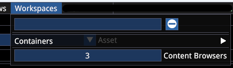
It is also recommended to specify more than one Content Browser window for easier navigation and file transfer within the editor.
The editor content is read from the SavedGames/ACE-Modder/mods/ folder.
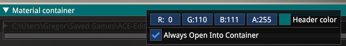
After creating a container, make sure you tick the checkbox so that any file you open is opened in its corresponding container. If you do not do this, new files will still open in their own separate window!
One suggested workspace setup looks like this:
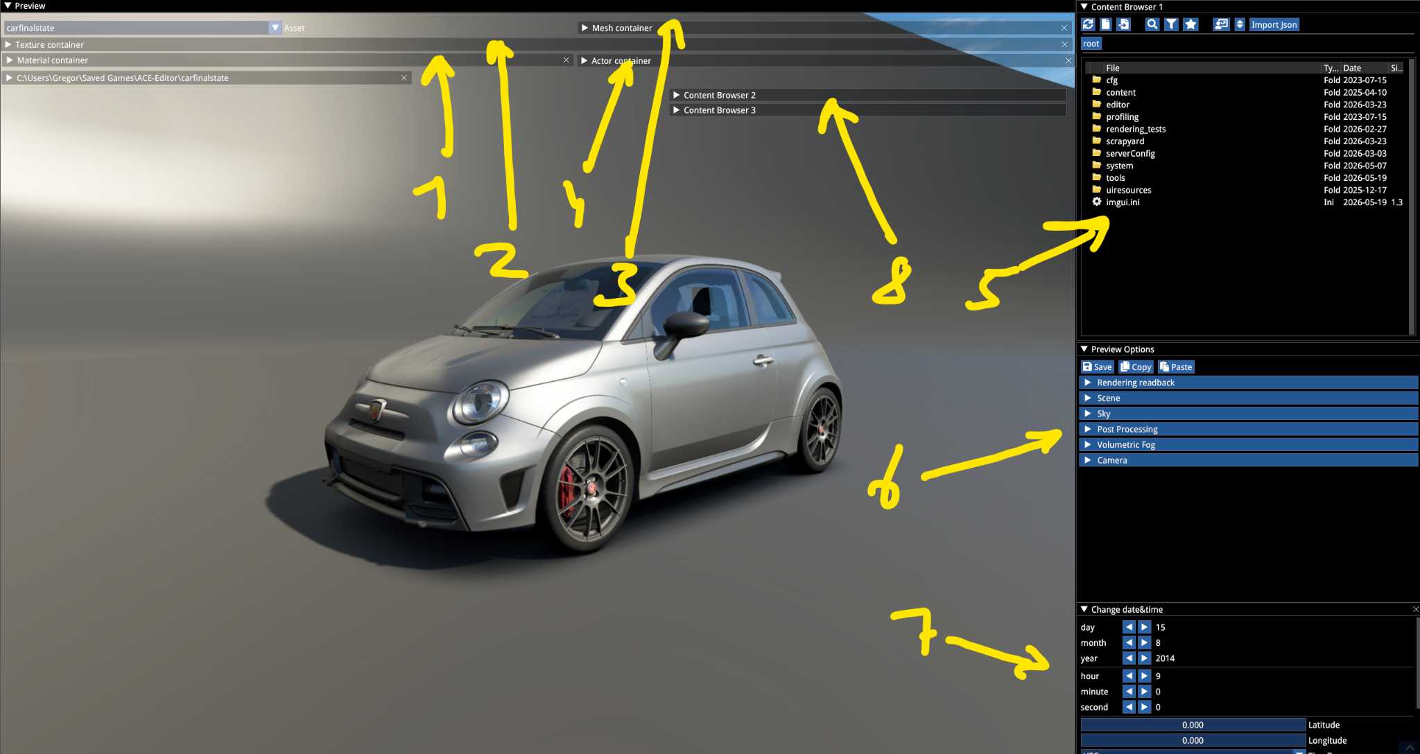
- Texture container
- Material container
- Mesh container
- Actor container
- Content browser (primary)
- Preview options
- Date & Time
Note how the Preview window is set to extend behind the containers.
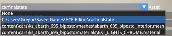
The Asset dropdown allows selecting between files that have a viewport appearance (meshes, materials).
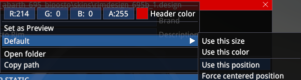
When not using a container for a specific type of file, when opening a new type of file, make sure you right click on its header and save the position and size you wish the file to open up the next time around. Otherwise the file will always open in a collapsed state.
WARNING
Closing Containers will close them without a prompt and their position and other properties will need to be set up again after creation via the Containers menu.
Your workspace settings are stored in the user/SavedGames/ACE-Mod/editor_workspace_data file. It is recommended to back up the file when you are content with your workspace for easy backup.
If for any reason you end up in an editor state or configuration that prevents it from being restored after launch, remove that file to reset the editor to its default state.
Edited and unsaved files are indicated in the file header with an asterisk (*).

Preferences
Settings -> Preferences menu allows you to make certain setup changes to the editor.
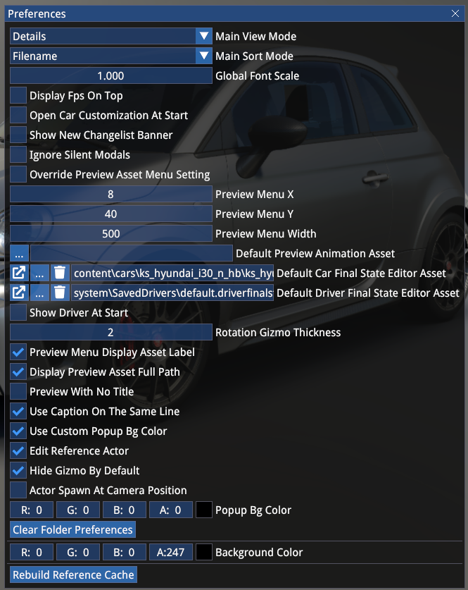
The settings should be self explanatory.
The above configuration shows a preferred setup of the lead content artist.
2. FBX REQUIREMENTS
A car is made up of the following mandatory, separately exported mesh files in .fbx format:
- Exterior
- Interior
- Rims (LF and RF mandatory — LR, RR only required to be separate when they are a different dimension)
- Blurred Rims (same)
- Tyres (same)
Optionally, the following meshes can be exported as separate files:
- Steering wheel (in this case it must be excluded from the interior)
- Seatbelt and/or Safety net on
- Seatbelt and/or Safety net off
- Brake discs (LF, RF — LR, RR only required to be separate when they are a different dimension)
- Devices or gauges
- Numberplates (F and R)
Each of these separate meshes must be exported from the 0,0,0 pivot of the scene with default rotation (Y-up) to remove any additional offset when attached to their parent bone.
E.g. when separate, the steering wheel, wheel meshes, disc etc. must be exported with all transformation and rotation first temporarily removed if the source scene (in Blender or 3DS Max for example) is saved with each item in its correct place.
Fbx files are to be exported with Y-up orientation, just like in AC1.
We differentiate between skeletal and static meshes. Skeletal meshes include a bone skeleton hierarchy for animations or parts attachment.
BONE STRUCTURE
EXTERIOR Mandatory Bones
CAR_BODY— the root bone of the car exterior, every other exterior dummy must be nested under itHUB_LFandHUB_RF— front hub bones follow suspension movements and they are rotated by the steering animation. It is recommended to align them to correspond with the physical characteristic of the front uprights, since contrary to AC1, even in-game the rotation is driven by the mesh dummy and not the physical suspension geometryHUB_LRandHUB_RRSUSP_LF,SUSP_RF,SUSP_LR,SUSP_RR— must be nested under theHUBbones, they are parent bones for the brake caliper, only follows hub movements, not wheel rotationDISC_LF,DISC_RF,DISC_LR,DISC_RR— must be nested under theHUBbones, they are parent bones for the brake discs, they follow wheel rotationWHEEL_LF,WHEEL_RF,WHEEL_LR,WHEEL_RR— must be nested under theHUBbones, they are parent bones for the rims — they follow wheel rotationTYRE_LF,TYRE_RF,TYRE_LR,TYRE_RR— must be nested under theHUBbones, they do not follow wheel rotation, since the tyre rotation animation is done by transforming the UV channel, the mesh itself is static and the only movement is the tyre flexing manipulation at the contact patch
EXTERIOR Optional Function Bones
WIPER_START_1,WIPER_END_1— these bones must be placed at the two ends of the wiper blade (nested under the wiper dummy that the blade is attached to as well) and they are mandatory for the correct functionality of the windscreen wipers. When there are more than one wiper, the suffix should be_2for the second wiper. The first wiper must be the one that wipes right in front of the driver.
TIP
Currently only 2 windshield wipers are supported and rear wipers are not supported (they can be animated but they won't wipe off any drops).
MIRROR_1andMIRROR_2— must be placed in the centre of the left (1) and right (2) side mirror planes, with Y-up, no rotation. They will serve as the projection point of the mirrors in Multi/VR mirror rendering mode.
EXTERIOR Arbitrary Bones
While not mandatory, it is recommended to use the following naming convention for other optional, non-functional bones (all caps):
DOOR_LF, DOOR_RF, DOOR_LR, DOOR_RR, FRONT_BUMPER, REAR_BUMPER, WING, DIFFUSER, HOOD, TAILGATE, PLATE_R, PLATE_F etc.
INTERIOR Mandatory Bones
COCKPIT_HR— root bone of the car interior, every other interior dummy must be nested under itSTEER_BASE— base bone for the steering wheel animation
INTERIOR Optional Function Bones
SEATBELT_ON,SEATBELT_OFFSAFETY_NET_ON,SAFETY_NET_OFF
Attachment bones for the seatbelt and safety net meshes, they react to visibility requirements in different scenarios (showroom will show the OFF state, in-game will show the ON state).
MIRROR_0— cockpit mirror, must be placed in the centre of the cockpit mirror plane without any extra rotation
INTERIOR Arbitrary Bones
DOOR_LF_INT, DOOR_RF_INT, PEDAL_ACCEL, PEDAL_BRAKE, PEDAL_CLUTCH, SHIFTER_0, SHIFTER_1 etc.
When the steering wheel is a dedicated mesh and has a skeleton for the shifter paddles, it is recommended to use the following naming convention:
STEER_HR— parent bone inside the steering wheel meshPAD_UP,PAD_DWetc.
IMPORTANT
By default, each separate object inside the fbx is treated as a bone, so in order to make sure the fbx file is optimized, make sure you use one of the following naming conventions for non-dummy objects, which will remove them from the bone skeleton after import:
g_example_objectnameGEO_example_objectnameRT_example_objectname
Here is an example of a basic suspension hierarchy with the correct bone and object naming (using the first example above):
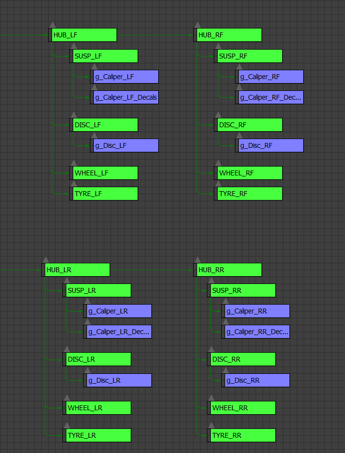
Any number of bones can be added in the skeletal mesh files, but it is recommended to not include more than what is necessary for basic functions, suspension animation and optional parts attachment.
For a detailed suspension rig and its dedicated requirements, see the sample mod's exterior fbx file.
WARNING
When you use a rigged suspension, the rigged bones with look-at constraint must have the X (red) axis pointing towards the corresponding DIR_ dummy (just like in AC1).
Any misalignment or incorrect setup can lead to the suspension geometry looking erroneous already in the showroom and finalstate editor, where the constraints are already enforced!
MATERIAL NAMES
The following material names are mandatory to follow a convention:
EXT_SKIN(EXT_SKIN,EXT_SKIN_2etc.) — materials for the main bodywork that usually include carpaint, livery and other skinnable parts. This is necessary to expose them for external livery editing and AI opponent colour variation (WIP)EXT_DISC— mandatory name for the brake disc materialEXT_WINDOWS(EXT_WINDOWS,EXT_WINDOWS_2etc.) — mandatory name for the exterior windows (can be multiple materials)INT_WINDOWS(INT_WINDOWS,INT_WINDOWS_2etc.) — mandatory name for the interior windows that exclude the windshield (can be multiple materials)INT_WINDSHIELD— mandatory name for the main windshield that has the high-res raindrop/wiper effects, can only be a single materialMIRROR_0,MIRROR_1,MIRROR_2,MIRROR_D(andMIRROR) — mirror materials
Each mirror should have its own material ID but only in the LOD 0. In LODs 1-3, the mirror material should be a single material called MIRROR:
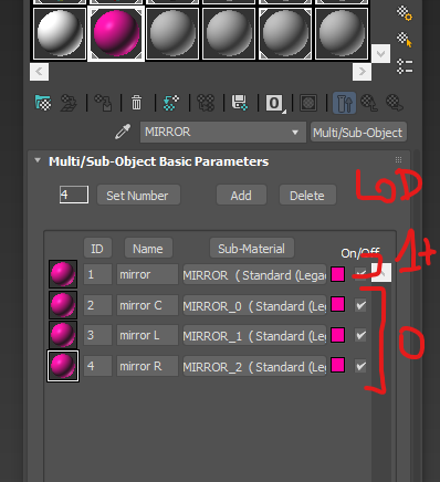
When the mirror is an LCD display, the material should be called MIRROR_D.
INT_DISPLAY(INT_DISPLAY_2,INT_DISPLAY_3etc.) — naming convention for digital displaysEXT_RIM— material for the static rimEXT_RIM_BLUR— alpha-blended see-through material of the blurred rim meshEXT_RIM_BLUR_STATIC— for the solid parts of the blurred rim meshEXT_RIM_DECAL(optional) — material for rim logosEXT_RIM_DECAL_BLUR(optional) — material for the blurred rim logo
As a general guideline, you can choose two ways of setting up materials:
- You can merge different materials into a single material where you use a splatmap (making use of the 4 unique channels in vehicle shaders) and colour and PBR maps, or
- You can separate each unique material with different properties into a new material. The game merges materials at runtime, so a large number of material IDs will not create a larger footprint — however, relying on a higher count of textures can create a larger video memory footprint even if the number of material IDs is optimized. As a result, we recommend explicit material separation and saving on the texture count.
Note: contrary to AC1, objects that only have a single material ID can now have multi/sub-object material assignments without reverting to the ID1 — this was an issue due to the outdated fbx library that was being used at the time, now this issue is fixed and there are no (known) caveats of material assignment from group materials.
UV AND VERTEX COLOURS
Certain functions are tied to the correct use of UV mapping and vertex colors.
Mirror UV mapping:
Mirrors require a specific UV mapping on 2 UV channels.
- Channel 1 should have the mirrors mapped like in AC1, reversed unwrap with 4:1 scale.
- Channel 2 should have the two side mirrors mapped to the centre of the map (in reverse orientation) with 2:1 scale. The central mirror should be mapped to the centre with 4:1 scale.
Light mesh vertex colours (for defining front/rear/left/right position):
| Position | Colour |
|---|---|
| Front Left | Red |
| Front Right | Green |
| Rear Left | Pink (R+G) |
| Rear Right | Teal (B+G) |
| Centre front | Yellow (R+G) |
| Centre rear | White (R+G+B) |
Brake disc vertex colours (for defining front vs rear disc glow):
| Position | Colour |
|---|---|
| Front | Red |
| Rear | Green |
Vertex colours should be assigned on each LOD stage, except for LOD 4 that has no separate brake and lights meshes.
EXPORTING ANIMATIONS
All car animations must be exported at 0-20 frames with only the implied bone structure selected.
Stacked animations can be exported (such as when the wiper is attached to an openable door), in which case the stacked-on animation must be exported with the animations removed the level above — meaning that in this example with the wiper, the wiper animation should be exported with the door hierarchy included but with the animations on the door dummies temporarily removed.
From 3DS Max, the following file export settings are used:
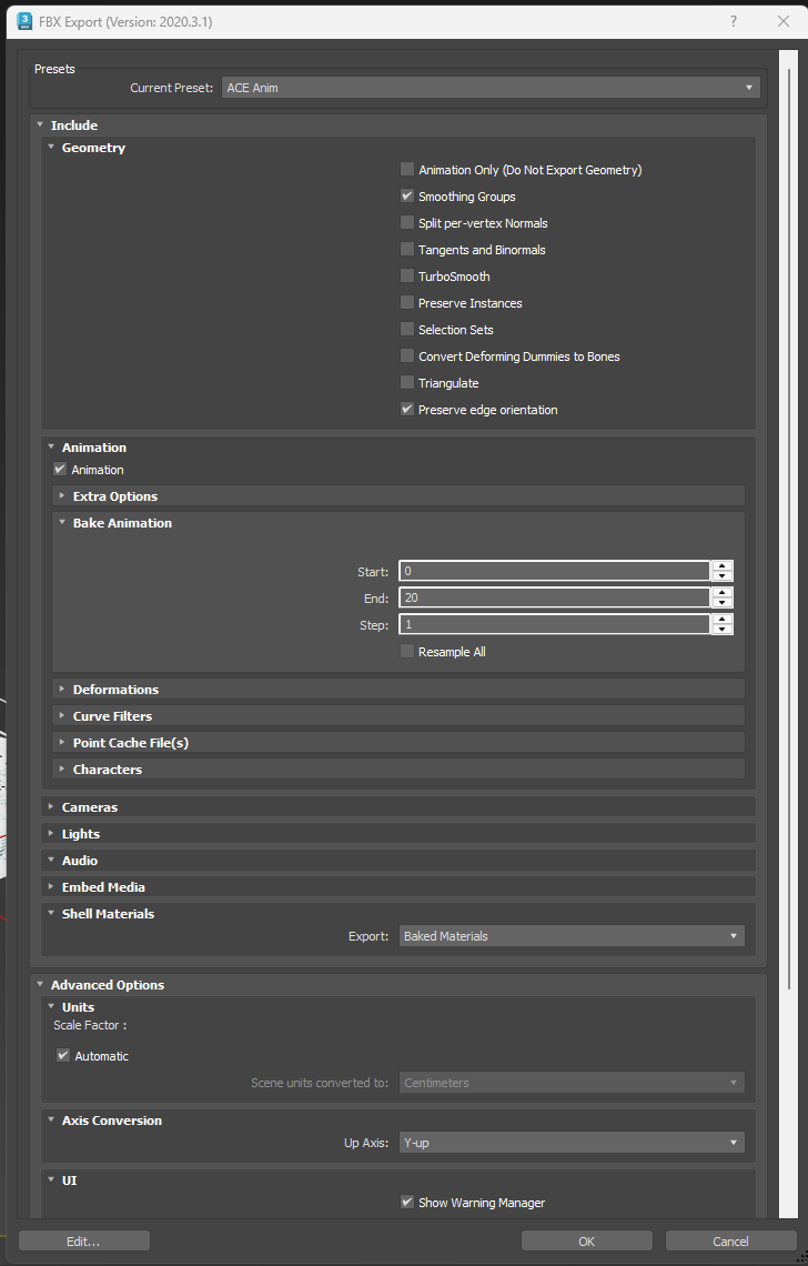
Note: animations can be disabled for regular skeletal mesh exports, but it should make no difference, a single export setting preset should work for all types of meshes.
3. TEXTURE REQUIREMENTS
Generally we recommend using png format in RGB8 colour mode. While textures with transparency are supported, we recommend using opaque textures and dedicated opacity alpha textures for opacity-dependent materials.
The recommended naming convention for textures is EXT_Skin_AO, INT_Mech_C etc., so EXT/INT prefix and type suffix.
Texture suffix naming convention:
| Suffix | Description |
|---|---|
AO | ambient occlusion |
AT | opacity |
C | colour/albedo |
D | splatmap |
E | emissive |
F | function mask |
R | roughness PBR |
M | metalness PBR |
CC | clearcoat level PBR |
CR | clearcoat roughness PBR |
S | scuff level |
AN | anisotropy |
In terms of levels, we use sRGB colour space for colour, AO, emissive and linear for PBR and functional textures.
For colour, we recommend avoiding extremes: the deepest black should not really go below sRGB 20/20/20 and colour peaks should not exceed sRGB 210 for non-metallic materials. For metallic materials, it can be pushed to 230 or slightly above but not further.
It is recommended to bake and include an AO texture (or level) for every single material, including glasses, small decals, grid meshes, otherwise it will clearly look out of place, especially in shaded scenarios.
FUNCTION TEXTURES
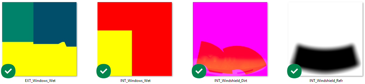
Windows
Windows wet functions require the following textures and rules:
EXT_Windows_Wet:
| Channel | Description |
|---|---|
| R | windshield area (255) vs side or rear windows area (0) |
| G | rain streak type — side glass (100), rear glass (150), windshield (255) |
| B | raindrop mask — side and rear (128), windshield (0) |
INT_Windows_Wet:
| Channel | Description |
|---|---|
| R | raindrops — yes (255) vs no (0) drops |
| G | rain streak type — rear glass (255) vs side glass (0) |
| B | placeholder channel |
INT_Windshield_Wet:
Same as INT_Windows_Wet.
INT_Windshield_Dirt:
| Channel | Description |
|---|---|
| R | damage area |
| G | dash reflection |
| B | static dirt mask — 0-255 gradient — recommended to make the wiper area near black, the rest white |
INT_Windshield_Refr:
Greyscale refraction mask, inside black, with a gradient on the edges (see above example).
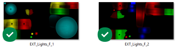
Lights
Lights require two function textures:
EXT_Lights_F_1:
| Channel | Front | Rear |
|---|---|---|
| R | daylight | regular light |
| G | low beam | brake light |
| B | high beam | fog/rain light |
EXT_Lights_F_2:
| Channel | Description |
|---|---|
| R | indicator (front and rear) |
| G | reverse (rear) |
| B | special function (front and rear) |
TIP
For modern headlights with alternating indicator/day running lights, set the DRL function as a special light (blue channel), which can be set to 0 emissive in the script when the indicators are toggled.
Functions can be stacked by combining channels, so red and green (yellow) in F_1 will function as both rear and brake light. This is often simpler than combining functions via the script itself.
LED
LED function maps have each RGB step of 10 assigned to a new function ID in the script:
RGB0   = ID1
RGB10  = ID2
RGB20  = ID3
...
RGB240 = ID25
RGB255 = ID26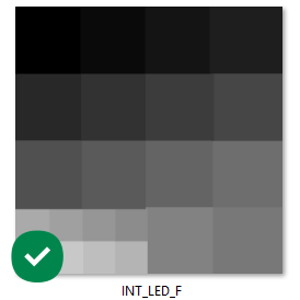
4. EDITOR IMPORT
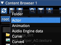
Before starting the import process, make sure you prepare a folder structure that can host all the different items we will need. Use the New Asset -> Folder button.
See an example below for the folder structure:
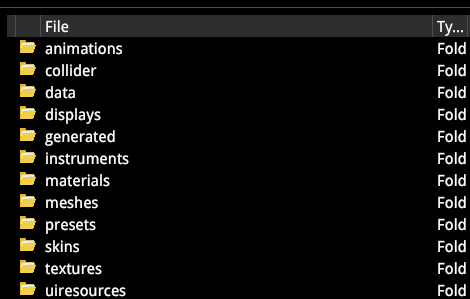
To start importing assets, we will be using the Import External Files button of the Content Browser.
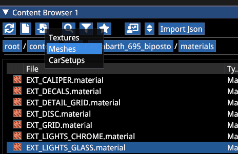
MESH IMPORT
Select Meshes in the dropdown.
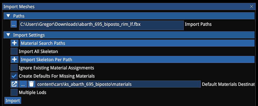
Let's see a skeletal mesh import:
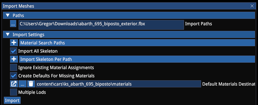
- Go into the Meshes folder of your mod car's folder
- Select the path of your fbx file
- Tick Import All Skeleton
- Untick Ignore Existing Material Assignments
- Tick Create Defaults for Missing Materials
- Specify the Materials folder of your mod car
For static meshes (tyres, rims, wheels, seatbelts and other meshes without a bone structure), do the same as above except for ticking Import All Skeleton.
The mesh editor allows you to define LOD rules, for example for the exterior:
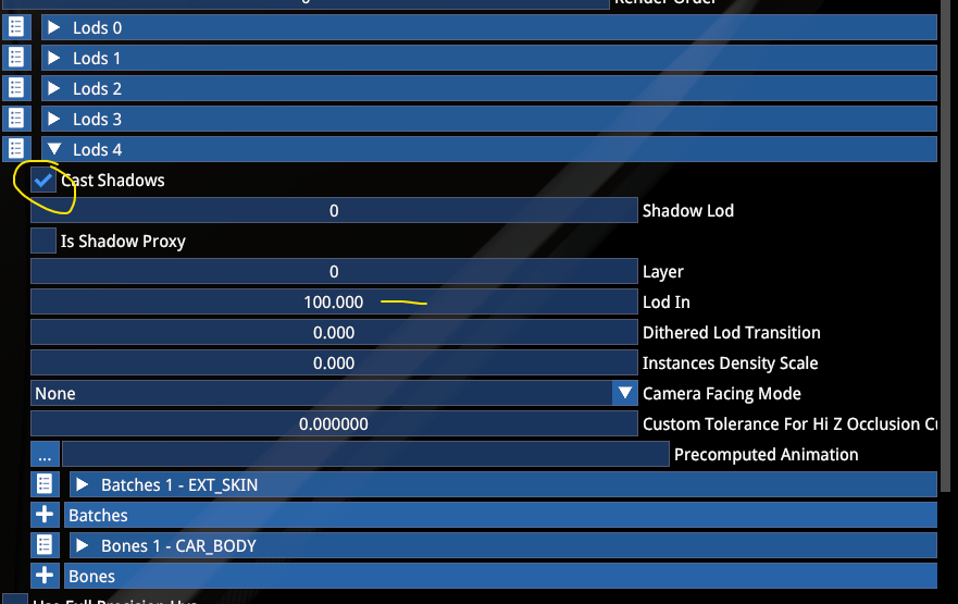
Our standard pipeline includes a total of 5 LOD stages (driven by the exterior):
| LOD | Description | LOD In Distance |
|---|---|---|
| LOD 0 | Player and showroom car | — |
| LOD 1 | Opponent car | 10 |
| LOD 2 | Progressive reduction | 20 |
| LOD 3 | Progressive reduction | 50 |
| LOD 4 | Simple mesh with 1-2 materials, only CAR_BODY, no functions or additional bones | 100 |
Make sure you tick Cast Shadows for each LOD stage and set a LOD In distance.
The interior has 5 LOD stages as well, but assigned differently:
| LOD | Description |
|---|---|
| LOD 0 | Player and showroom car |
| LOD 1 | First stage when high LOD settings are set |
| LOD 2 | First stage when lower LOD settings are set (matching COCKPIT_LR in AC1) |
| LOD 3 | Progressive reduction, matching exterior LOD 2 |
| LOD 4 | Progressive reduction, matching exterior LOD 3 (LOD 4 exterior has interior culled!) |
While it is not mandatory to follow this convention, the game is designed to work with these LOD stages, so the lodding behaviour and performance will only be comparable if these are respected.
For the interior and other meshes we have a slightly different setup:
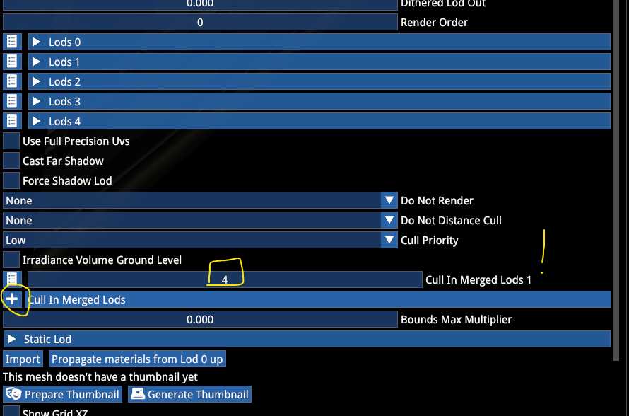
For the interior, rims, blurred rims, tyres, other attaching meshes, make sure the Cull in Merged Lods is populated with stage 4. This means the mesh will be removed when the simplified exterior is switched.
The interior should have the following Lod In settings: LOD 1 at 5, LOD 2 at 10, LOD 3 at 20 and LOD 4 at 50.
Tyres and rims should have 2 LOD stages (0 and 1) and LOD 1 should be set to LOD In at 20.
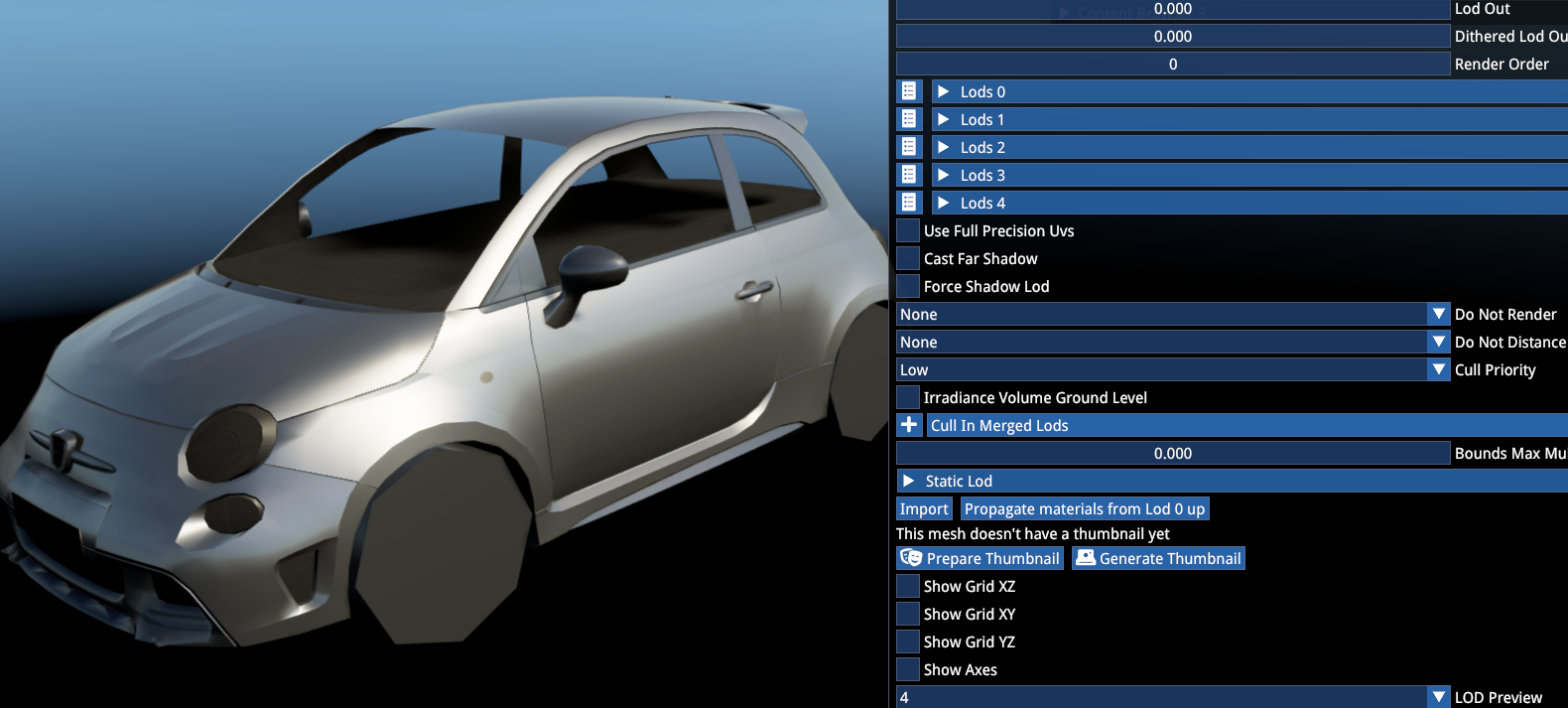
LOD 4 previewed with all other meshes other than the exterior culled:
While working in the mesh editor, you can use the Use Full Precision UV to preview the high-quality UV space.

NOTE
Make sure you disable this setting when all your meshes are set up and you start working on the car via the Finalstate Editor (see later). Both the Finalstate Editor and the game have the high-precision setting enabled by default.
TEXTURE IMPORT
Using the Import External Files button, select Textures in the dropdown.
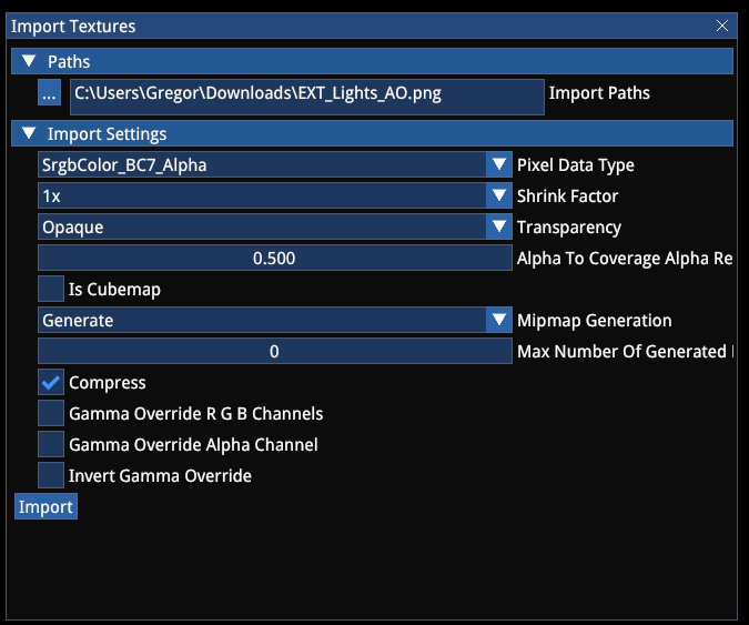
Generally the default settings will be sufficient, except for the Pixel Data Type field, which must be selected according to the type of texture:
| Pixel Data Type | Applicable Textures |
|---|---|
| Srgb BC7 | colour, AO, splatmap (detail mask), function mask, emissive mask, any texture that is meant to use sRGB colour space |
| Linear Colour | any colour texture that is meant to use linear colour space (when exported with RGB16 mode — not recommended) |
| Linear Greyscale | greyscale textures, such as PBR — roughness, metalness, clearcoat, clearcoat roughness, opacity |
You can use BC1 mode optionally when the texture is not visible degraded due to the more aggressive compression (ideal for splatmaps and masks with clear contrasts and no gradients).
Make sure the Compress checkbox is always ticked and make sure MipMap Generation is always enabled.
With certain textures, you can limit the number of mips to generate (default is 16), such as splatmaps, where the area separation is important even at distance. In this case it is recommended to not limit it more than 2 or 3 mip levels.
Note: after the texture is imported, changing any of the properties requires reimporting the texture with the Import button! (Unlike in Unreal for example where texture metadata can be edited independently from the texture itself).
SHADER TYPES
The following shader types are required for setting up a car:
| Shader | Usage |
|---|---|
UberVehicle | All exterior materials — uses exterior probe capture |
UberVehicleInterior | All interior materials — uses interior probe capture |
VehicleDisc | Brake disc |
VehicleLed | Emissive LED functions |
VehicleLight | Solid lights |
VehicleGlass | Exterior windows and lights glasses |
VehicleWindow | Interior side and rear windows |
VehicleWindshield | Main windshield with wiper effects |
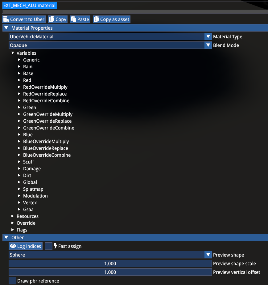
MATERIAL EDITOR
Select the correct material type in the dropdown.
Blend Mode:
| Mode | Description |
|---|---|
| Opaque | Fully opaque, opacity texture is ignored |
| AlphaToCoverage (A2C) | For materials that have binary opacity information |
| AlphaBlend | For glass materials |
AlphaTest and the other blend modes are generally not used for car materials.
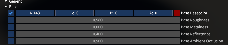
Base section includes the basic properties and resource checkboxes. Texture assignments will only take effect when they are also enabled in either the base or a dedicated channel.
Red/Green/Blue are splatmap channels, and they allow you to set up a total of 4 material properties in a single channel, with the RGB sections having their own detail maps as well. Additionally the Scuff section allows you to add a permanent scuffing to the material.
The splatmap channels can be used in two different ways:
- With a splatmap texture to define separate areas — you can separate 4 different material properties, such as paint, plastic, metal. Typical use case for
EXT_SKINmaterials. - With a stacked or mixed splatmap value — you can stack material properties for materials with more depth, such as leather where the base is the base PBR, one channel is the leather detail, another channel is the wrinkle detail and another channel is the crack detail. Typical use case for cloth and leather materials or solid materials where you would want to use more detailed scuff effects.
Each channel can Multiply or Replace the material properties of the base. Combine features can be used to stack overlay normal maps or a specific modulation of roughness behaviour when the channel's roughness texture is supposed to blend with the base roughness value (or texture).
Modulation section allows for another type of modulation blending for several material properties.
Scuff effect can be used with dedicated values for each splatmap channel, and a specific scuff intensity texture can be used to define which areas of the UV map are supposed to receive scuff effect.
In general, the UberVehicleMaterial's layout is shared by the other functional vehicle shaders:
UberVehicleInterioris identical with the exception of the probe capture reference.VehicleDiscincludes specific slots for blurred states.VehicleLEDincludes an emissive pass for the 26 LED function IDs.VehicleLightandVehicleGlassinclude the specific function emissive texture slots.VehicleWindowandVehicleWindshieldare used specifically for the different window/windshield glasses.VehicleRimshader includes the face and gamma properties for fading between static and blurred state and require specific flags to be used. The rims require 3 separate shaders to be used.
For a correct setup of these unique materials, see the sample mod. Watch especially the General sections, unique checkboxes and the Flags section.
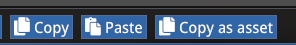
Materials can be simply copied between each other with the Copy and Paste buttons at the top:
Often materials need to be duplicated for different customization sections of the car, in which case it is recommended to use material override:
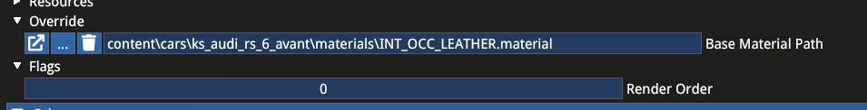
WARNING
Make sure you don't use the material override between different projects! Otherwise the cross referencing will result in one car not working without the other present.
After parenting, the child material can still be edited by flagging the changing property unique.
This is useful when you for example have different leather materials with only the colours changing, so you have a single material for PBR reference and the colour section flagged unique for the different materials:
5. CAR ACTOR
The primary container of all car information (without physics data) is the Car Actor. The guide will go through each section in the order of importance (mandatory sections first), and certain sections will be also discussed in more detail in their own chapters — such as cameras and especially customization.
Use the New Asset -> Actor button to create it for your mod in your project's root folder. Use lower case.
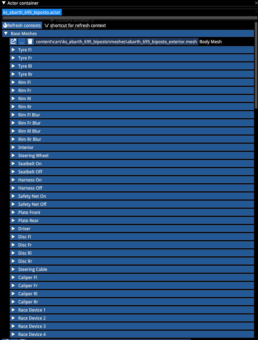
MESHES
Firstly, we must assign the mandatory base meshes. These don't require an Attachment Bone definition, as they are hardcoded already:
- Exterior
- Interior
- Tyres
- Rims
- Blurred rims
Typically optional meshes include:
- Steering wheel
- Seatbelt or Harness
- Safety net
- Registration plates
- Steering cable
- Racing devices
NOTE: The Driver slot as well as the Tyre Texture slot below the Base Meshes section are obsolete.
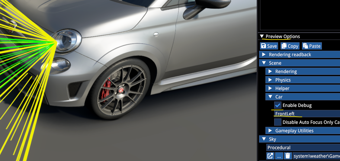
LIGHTS EMITTERS
Lights emitter definitions for physics-based lights on the car:
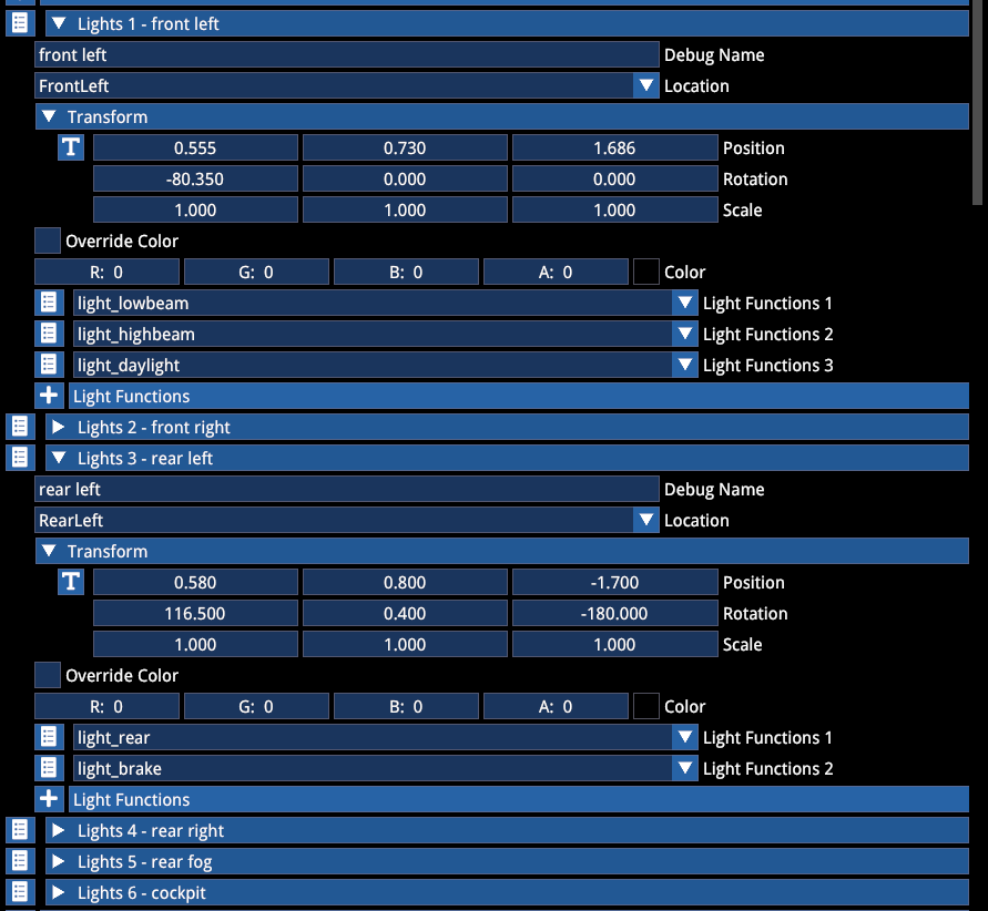
Each light source can have their functions assigned and a colour override from the hardcoded defaults (white and red). Typically 6 emitters are used (see the example array above). Abusing the number of emitters can have serious performance implications.
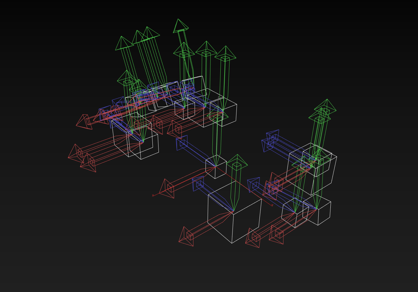
Once the car is assembled enough to show up in the Finalstate Editor, light positions can be previewed in the scene preview Scene/Car debug by ticking the Enable Debug option. The debug cone will show up when the light is actually active via the instrumentation.
FUNCTION SCRIPTS
Function scripts can be assigned in the following section:
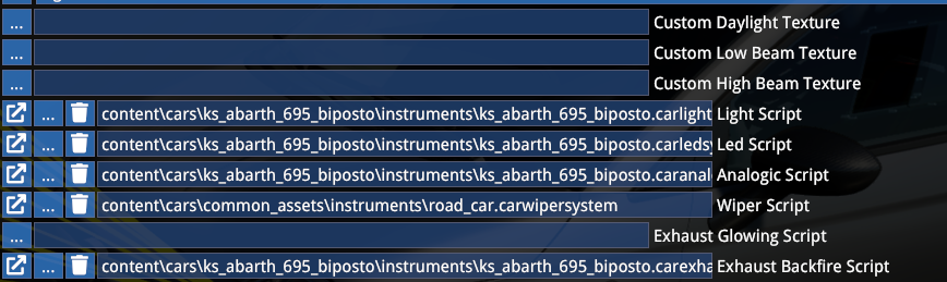
Only assign the relevant ones. See the example mod for more information.
PREVIEW TOOLS
This section allows you to set up the car's showroom stance (it is only used in the showroom, and ignored in-game). The Customization and Runtime sections are not relevant to use, all those functions can be accessed via the Finalstate Editor later on.
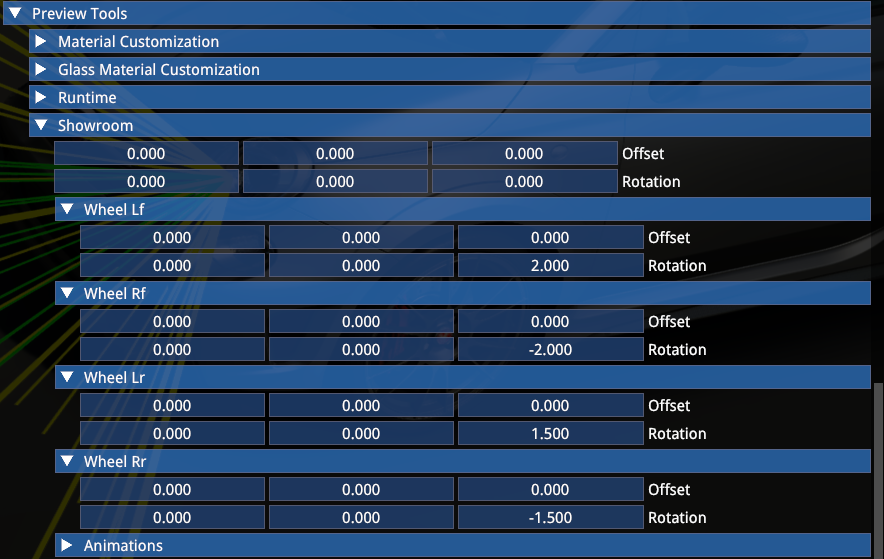
In this example the model remains in fbx position and -2 and -1.5deg camber is added to the front and rear wheels for the showroom, respectively. In-game the live camber values are used.
MIRRORS
The mirrors section allows you to set up the mirrors for each mode:
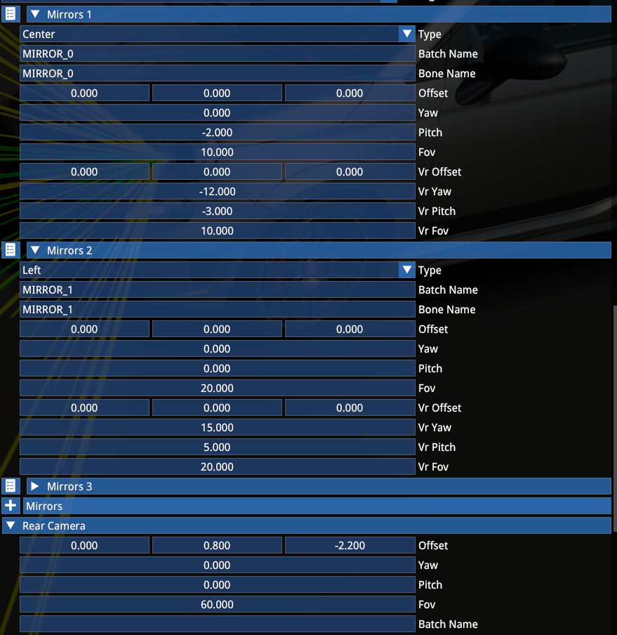
The array should only include the mirrors the car actually has, so in case of 2 or less, only specify the relevant one(s):
| Mirror | Description |
|---|---|
| Mirror 1 | Central |
| Mirror 2 | Left |
| Mirror 3 | Right |
Rear camera settings are used both for display cameras and the Virtual Mirror capture! It must be set up for the VM even when the car has no physical mirrors.
VR-prefixed offset/yaw/pitch settings are specifically for the Multi/VR mode.
TIP
Only set up the VR-prefixed items once you have already set up the default driving camera, since changing the default view later will also offset the VR mirror image.
LIGHTS AND LEDS
Material name array specifies which materials should be affected by lights and LED functions. List all materials that are implied here.
The Leds section underneath the Batch Names is obsolete.
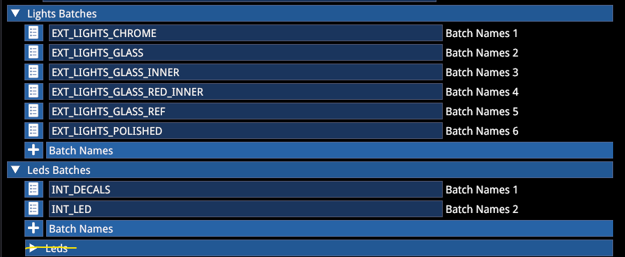
Note that the function enums are consistent across all materials, meaning that ID1 will have the same function in INT_DECALS and INT_LED as well.
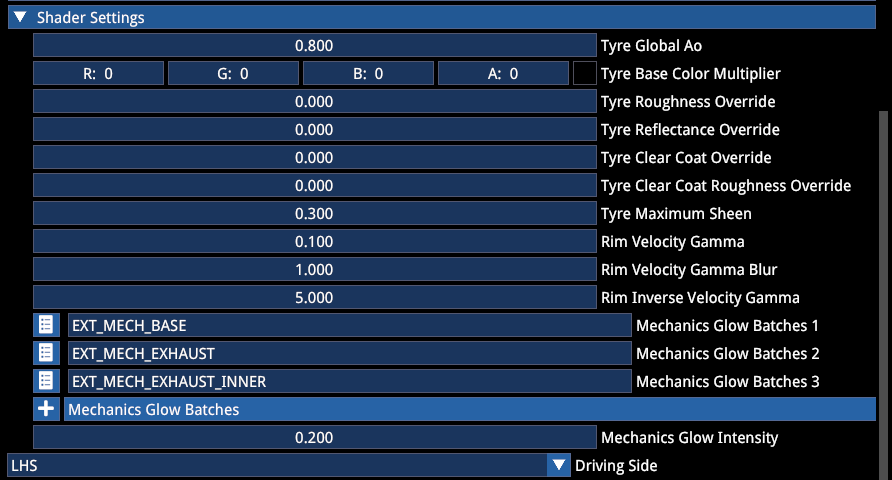
SHADER SETTINGS
These are used to define certain shader effects:
| Setting | Description |
|---|---|
| Tyre global AO | Additional AO mask on the tyre. Higher value = more shadow, lower value = less shadow. Use 0 for open wheelers and 0.8 for closed wheel wells (such as GT race cars) |
| Tyre Colour and PBR override | Allows unique base tyre shader values for the car. Leaving everything at 0 will retain what's applied on official content |
| Tyre Maximum Sheen | Glossy chrome sheen amount on fresh tyre (showroom and after spawning), wears off after a short bit of driving. Recommended values: 0.5 for modern F1, 0 for road tyres |
| Rim Velocity values | Start from the provided baseline, sets the transition between static and blurred rim meshes/materials |
| Mechanics Glow Batches | Materials with emissive textures that should be affected by exhaust temperature-induced glow |
| Mechanics Glow Intensity | Maximum emissive value multiplier at the highest reference temperature |
| Driving side | LHS, RHS or Centre — defines which door is opened in the intro sequence |
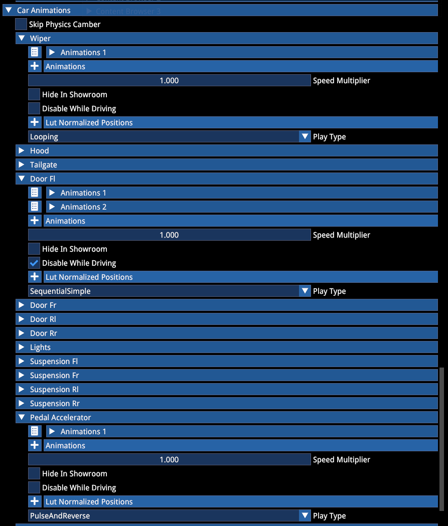
CAR ANIMATIONS
Animation can be defined for predefined functions, and also an infinite number of optional animations can be added for cosmetic purposes or for certain physics properties, such as active aero. The example below shows the usual play types (Looping, Sequential Simple, Pulse and Reverse) where they are typically assigned.
For information on driver animations, see the corresponding documentation.
Sequential LUT (lookup table) animation:
An example for an Optional animation with multiple stages (Sequential LUT). With these, you can define the steps for the frames you want the animation step through with a lookup table:
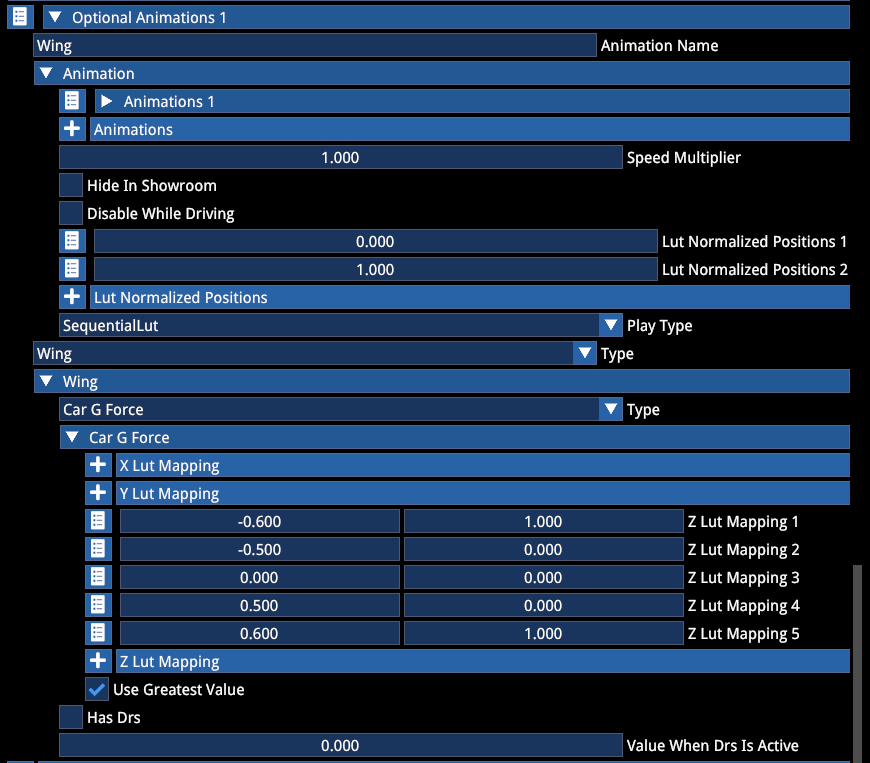
In this example above the animation is linked to longitudinal g-forces, it opens both under hard acceleration and deceleration. Besides this, you can assign other controllers, and by ticking the Use Greatest Value, the animation will play based on the highest momentary input value.
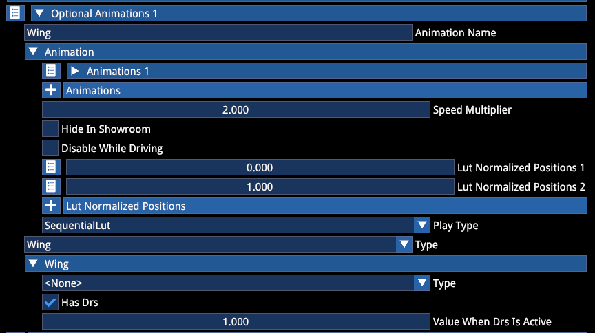
Another example for a DRS driven animation:
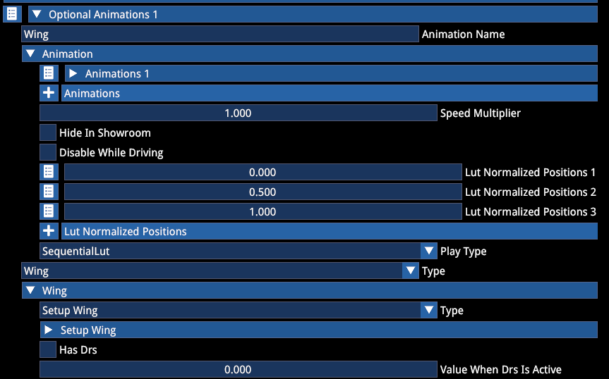
Another example for setup-driven animation (when the wing setting in the setup is visualized on the car):
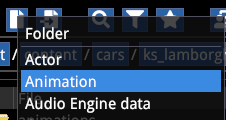
To import car animations, you have to select New Asset -> Animation. Do this in a dedicated Animations folder in your mod car's folder.
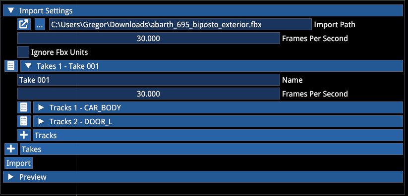
In the import settings select the path, and press Import. The Take will then autopopulate with the included bones:
BODY SHADOW DECAL
These properties allow you to define the fake body shadow size and intensity.
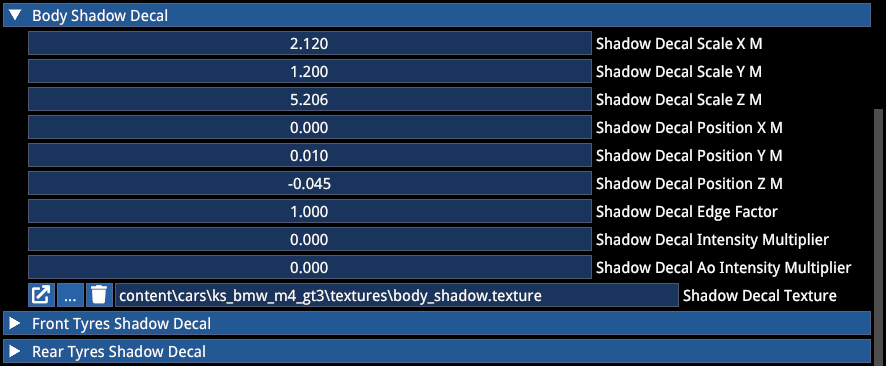
Start from the values above and adjust to taste, make sure the decal is moved to the ground level (Position Z).
The texture should look something like this:
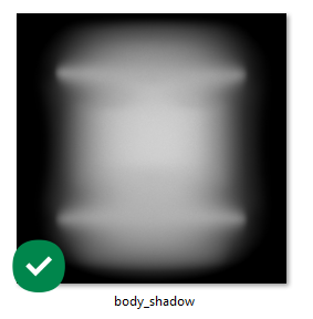
It is recommended to bake at least the rims (without the tyres) into the shadow for the best result.
The tyres have their own shadow decals defined in the Tyreesh files, they are not defined through the Actor. The sections for Front and Rear Tyres Shadow can be ignored here.
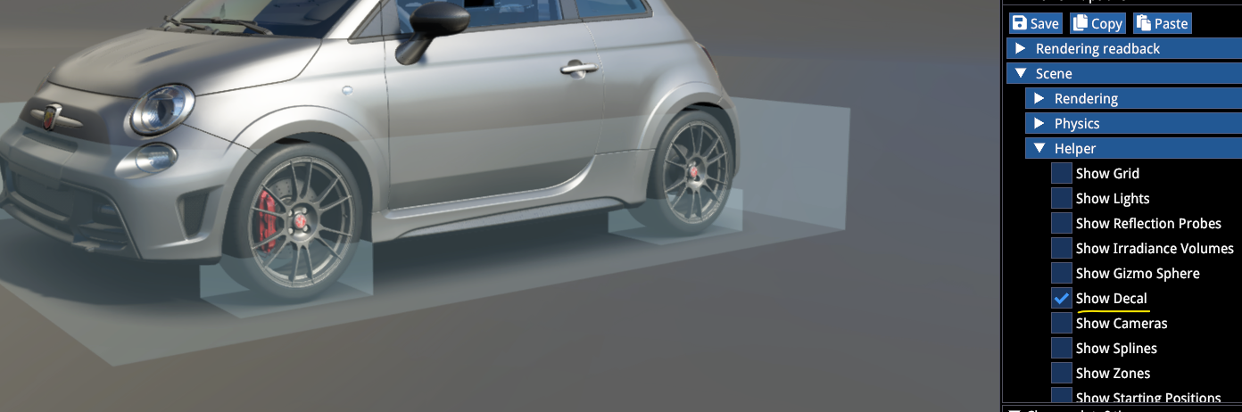
The decal itself can be previewed by using the Decal visualization debug in the Preview Options -> Scene -> Helper section when the Finalstate Editor is active.
PARTICLE EMITTERS
These include car and tyre effects for spray, dust and smoke, as well as exhaust backfire:
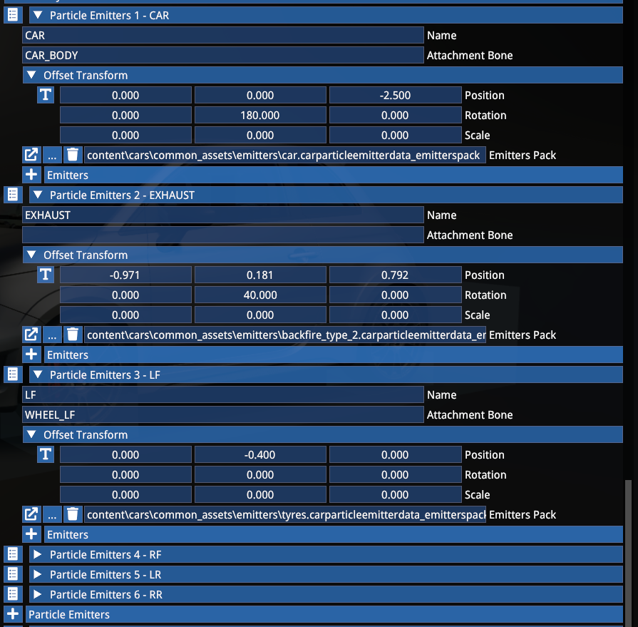
The mandatory ones are CAR, LF, RF, LR and RR.
Emitter packs are hardcoded for mods and they are aligned with official content.
EXHAUST emitters (optional):
| Type | Description |
|---|---|
| Type 1 | Only blue flame (road cars) |
| Type 2 | Mostly blue flame with the occasional small flame (racing cars and supercars) |
| Type 3 | Mixed flame with occasional large flame (hypercars or tuned cars with characteristic flames) |
For the CAR and WHEEL emitters, use the recommended transformations shown above in the example.
NUMBER DECALS
This allows you to assign dynamic numberplates with specific background texture and fonts.
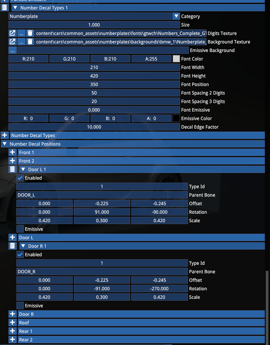
The Number Decal Types section defines the layout — the visual appearance of the decal, while the Number Decal Positions section defines the decal position on the car itself. You can add an infinite number of decals and assign a different ID sets, which you can then assign per visual preset (see Customization section later).
CAMERAS
Cameras include the following:
- Drivable cameras (cycled via the F1 key)
- Onboard cameras (cycled via the F6 key)
- Showroom cameras (pannable and internal showroom camera in the menus)
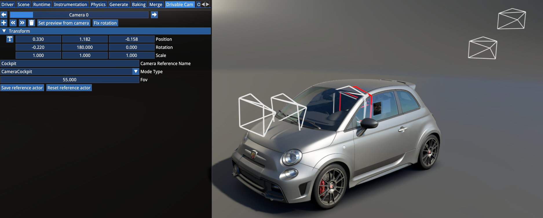
Drivable Cameras
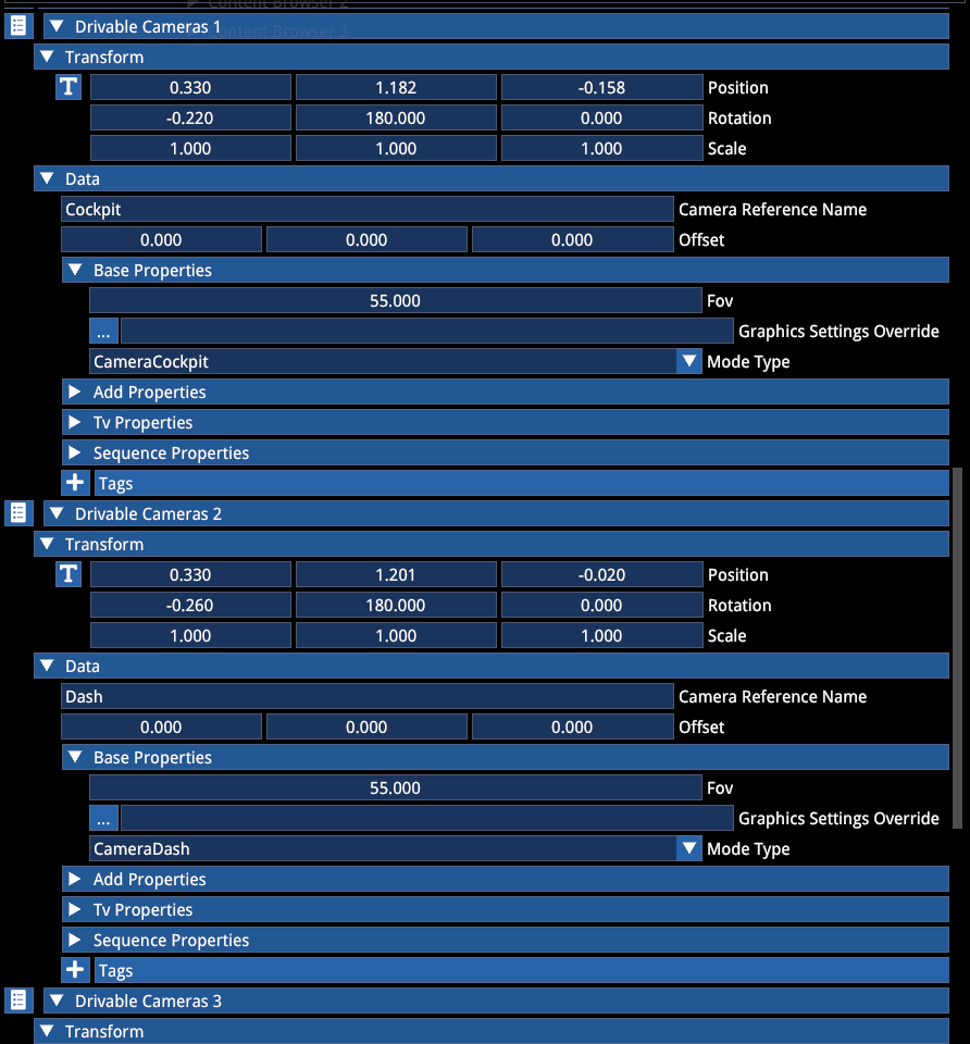
Drivable Cameras include a total of 6 cameras:
| Camera | Mode Type |
|---|---|
| Cockpit | Camera Cockpit |
| Dash | Camera Dash (forces driver model and steering wheel to be hidden) |
| Bonnet | Camera Fixed |
| Bumper | Camera Fixed |
| Near Chase | Camera External |
| Far Chase | Camera External |
The correct setting is necessary for the correct sound mix to be used when the camera is active.
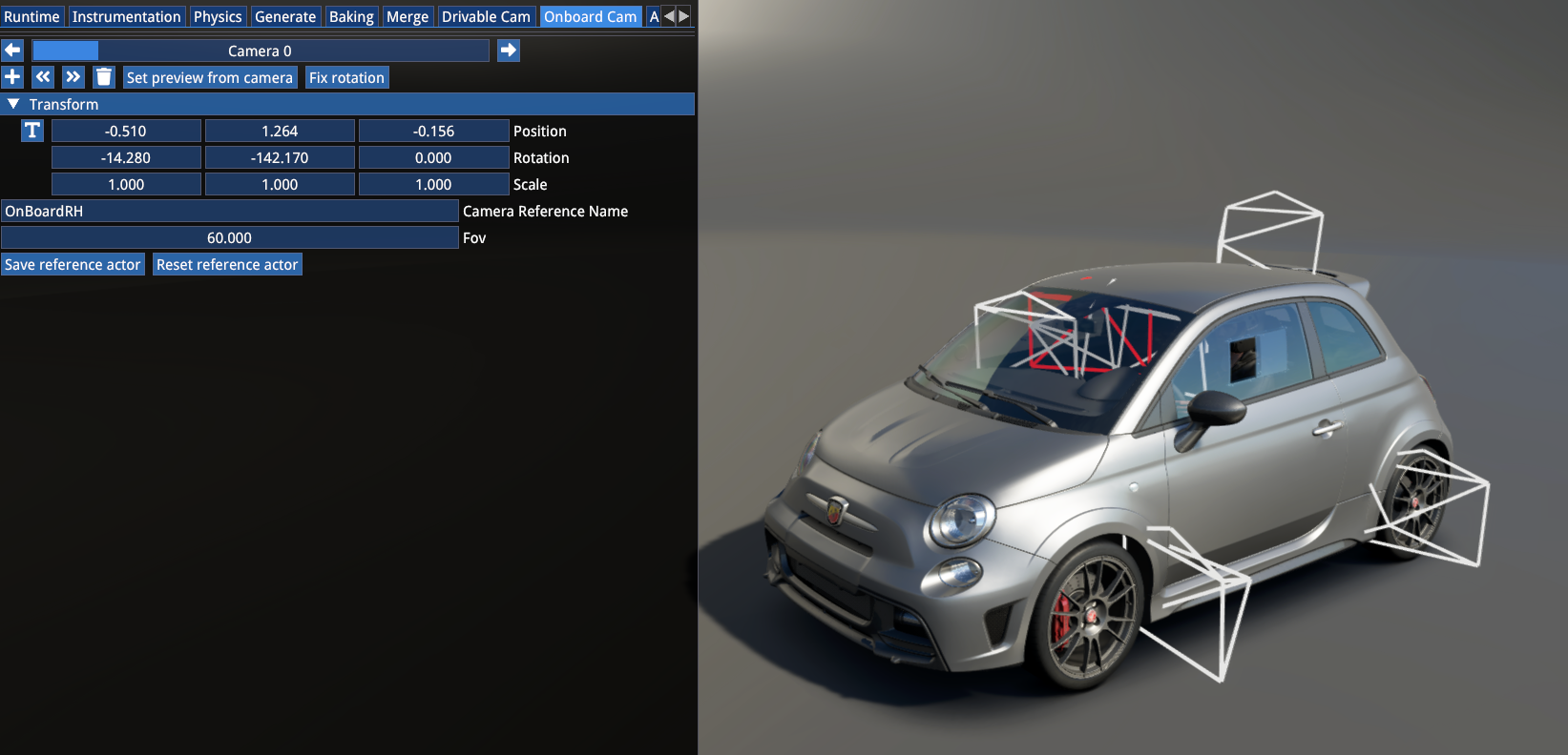
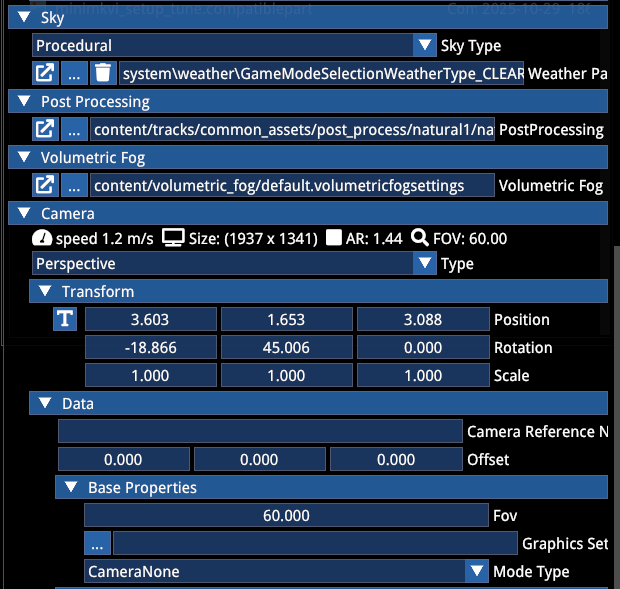
Onboard Cameras
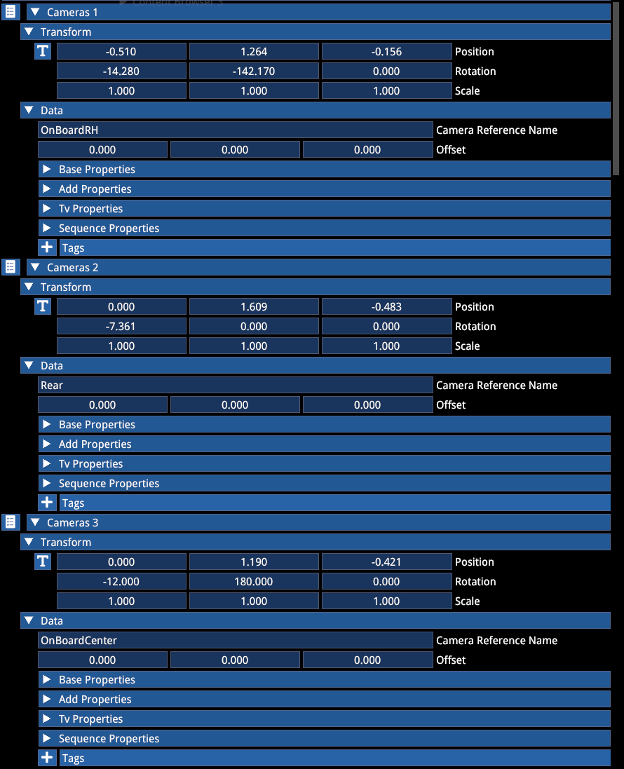
These cameras can be added in the Cameras section. The Camera Reference Name can be used optionally to give the camera a friendly name for future reference. The default FOV of these cameras is hardcoded and not used from the actor.
The Fixed setting under Base Properties removes the additional g-force effects from the camera. This can be set for each camera instance, as well as a unique FOV value.
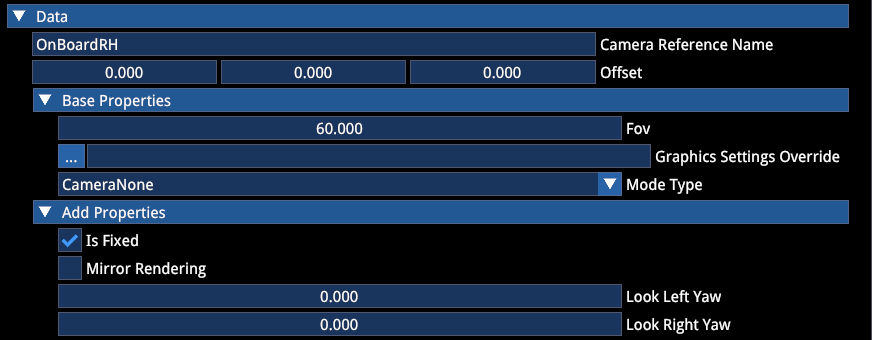
The cameras should have Camera None mode type set.
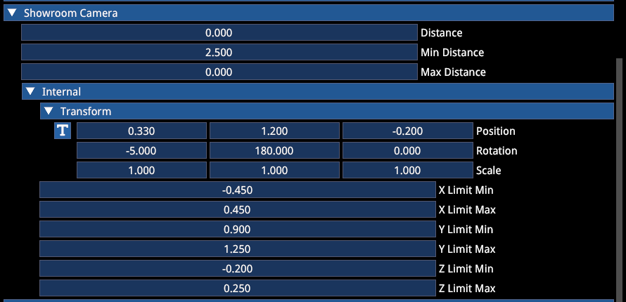
Showroom Camera
These settings refer to the behaviour of the panning camera and the internal camera.
Start from these settings and adjust depending on your mod car's dimensions and seat position:
DASH DISPLAY
Dash display definitions must include the material name that the image is rendered over and the resolution of the texture used:
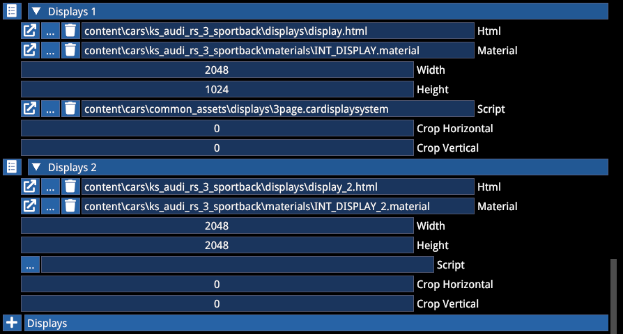
In this example the car has 2 separate displays, one with 2:1 aspect ratio, while the other with 1:1.
The script of the dash display is stored in html format and it references images from the mod car's \display\ folder.
The Dash-In-Hud setting defines whether the digital display is supposed to show up in the HUD display widget when enabled:

| Value | Description |
|---|---|
-1 | No display should show up (either because there isn't one or the display is a digital clock or similar) |
0 | Main display shows up |
1 | Second display shows up |
2 | Third display shows up |
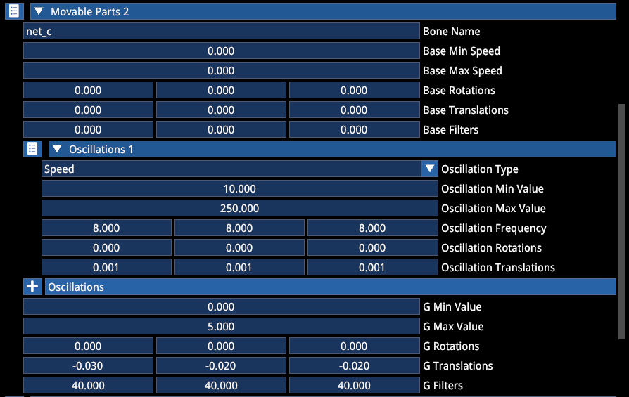
DAMAGE AND MOVING PARTS
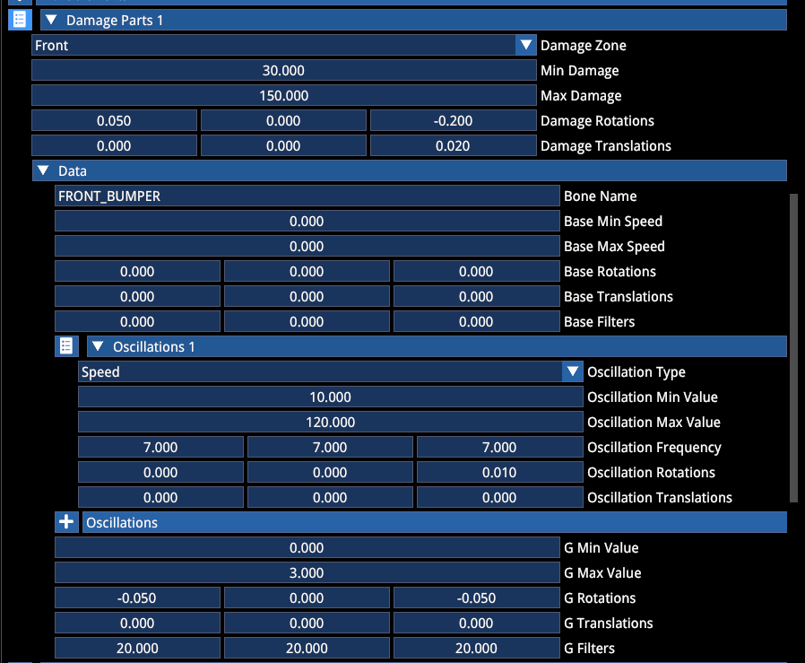
Damage parts are bones that react to impact and move or rotate in a predefined direction and amount.
The above example is for a front bumper, which belongs to the FRONT area (damage zone) and reacts to speed-based oscillation when damaged and rotates and moves on the Z axis upon impact, as well as reacting to g-forces when damaged.
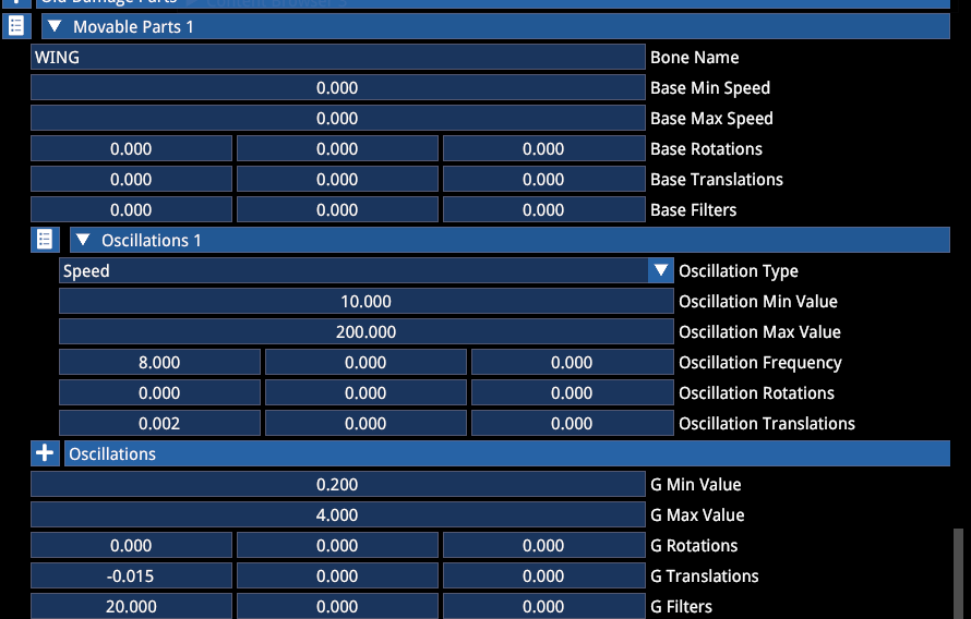
Moving parts are bones that react to g-forces or speed with movement or oscillation, typically safety nets but can also be applied to certain elements of the car itself (such as wings, aerials etc.)
Example for rear wing:
Example for safety net:
6. CUSTOMIZATION
Contrary to AC1, the car is not a working entity with the simple collection of its meshes. Customization definitions are used to establish the car's default "finalstates". It means that the materials and colours applied on the meshes are not necessarily the ones that will be visible, since with customization the preset colours will be applied on the materials included in customization.
The minimum requirement for customization for a car to work includes the following:
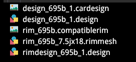
- 1 compatiblerim — the set of rims paired with the car, minimum 1 is required — references the rimmesh file and corresponding tyremesh file
- 1 mechanical preset — mechanical definition, minimum 1 is required — references the default compatiblerim file and the visual preset
- 1 visual preset — cosmetic definition state for customizable materials, minimum 1 is required, references the cardesign file, default rimdesign file and number decal set (optional)
- 1 cardesign file — references the design file and the available compatiblerim files allowed for that design
- 1 design file — customization rules (list of materials included in the customization and their rules)
- 1 rimmesh file — a file that contains a pair of rim meshes and all rim design files
- 1 rimdesign file — a file that contains the customization rules for the rim
Note that only the existence of these files are required, the design files can be left empty if no customization is desired on the car. However, each material that is defined in the design files with multiple colour options must have a default colour defined in the visual preset — both for the car and the rim!
VISUAL PRESET
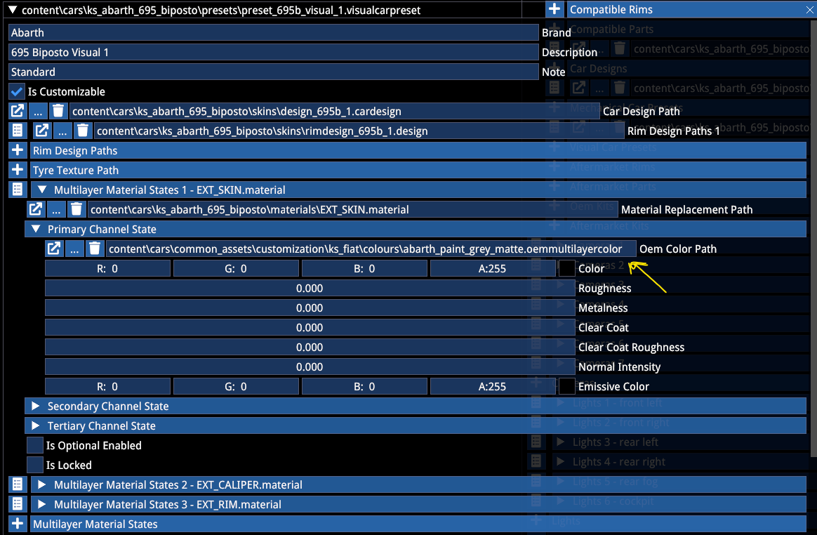
In this example the car has 3 customizable materials, 2 via the design file (Skin and Caliper) and 1 via the rimdesign file (Rim). In the visual preset each has a default colour defined from the array of available colours, which defines the default finalstate of the car (e.g. matte grey bodywork).
Note the cardesign path reference and the rimdesign definition.
Note the isCustomizable flag — when this is unticked, the car will be locked into its default state — however the above files are still necessary for defining what that default state is!
MECHANICAL PRESET
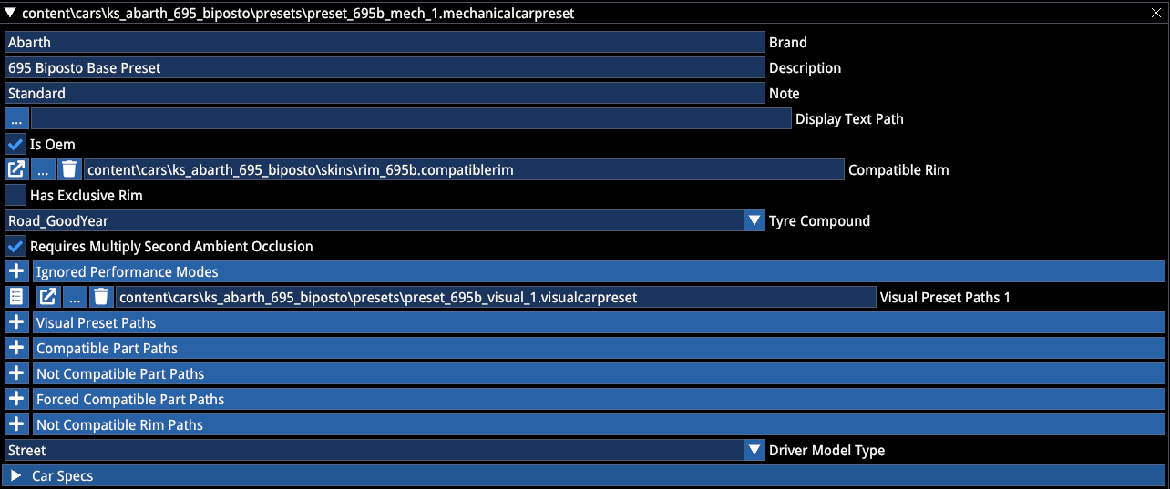
The mechanical preset must include the list of compatible visual presets and the default compatible rim (not an array).
It also contains the numeric Car Specs that show up in the UI — these can be defined per mechanical variant.
The point of mechanical presets is to be able to create different variants of the car through the part definitions:
- Compatible Part Paths — list of installed (but removable parts)
- Not Compatible Parts Paths — list of not installable parts on this preset
- Forced Compatible Part Paths — list of forced (non removable) parts
- Not Compatible Rim Paths — list of not allowed rims when this preset is selected
Driver model type can be defined here whether it's meant to have a street or racing driver model.
COMPATIBLERIM
A CompatibleRim file defines a set of two pairs of rims and tyres assigned to the car.
Additionally it can define a delta showroom stance modifier for when the overall wheel dimension is different from the default, so a modification of the showroom position is required when installed.
This is also where an installation offset can be added to the wheels both for the showroom and in-game.
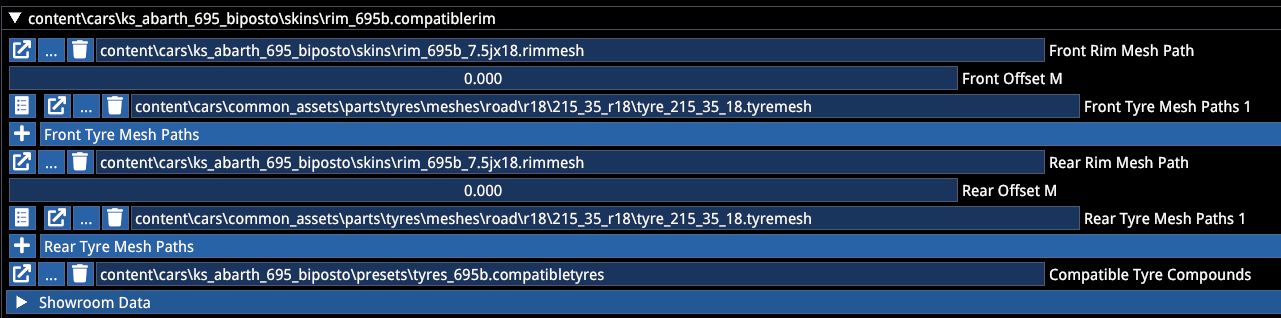
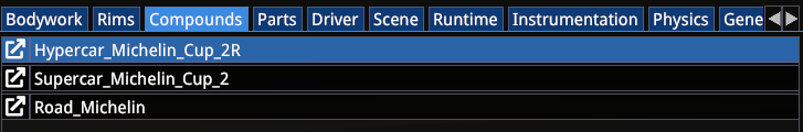
The CompatibleTyre file reference includes the allowed tyre compounds for this set of wheels:
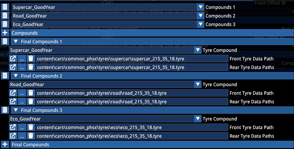
Here the 3 visual compounds are matched to the physical tyre files. Note that any physical tyre can be matched with any visual compound — but it is generally recommended to make sure the visuals represent the installed tyre type.
CARDESIGN
CarDesign files are a container to pair a specific design file with the available rims it is allowed to be paired with.
It can contain 1 design file and any number of compatiblerim files:
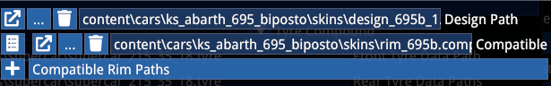
In this example, only one set of wheels is defined.
DESIGN
Design files where the possibilities become almost endless.
Here you can define which materials of the car are to be involved in customization, either with selectable colours or by inheriting custom colours from other materials or being optional selections.
In this example you can see how the primary channel (R) of the EXT_SKIN material allows both OEM colour customization and free picker choice including PBR values:
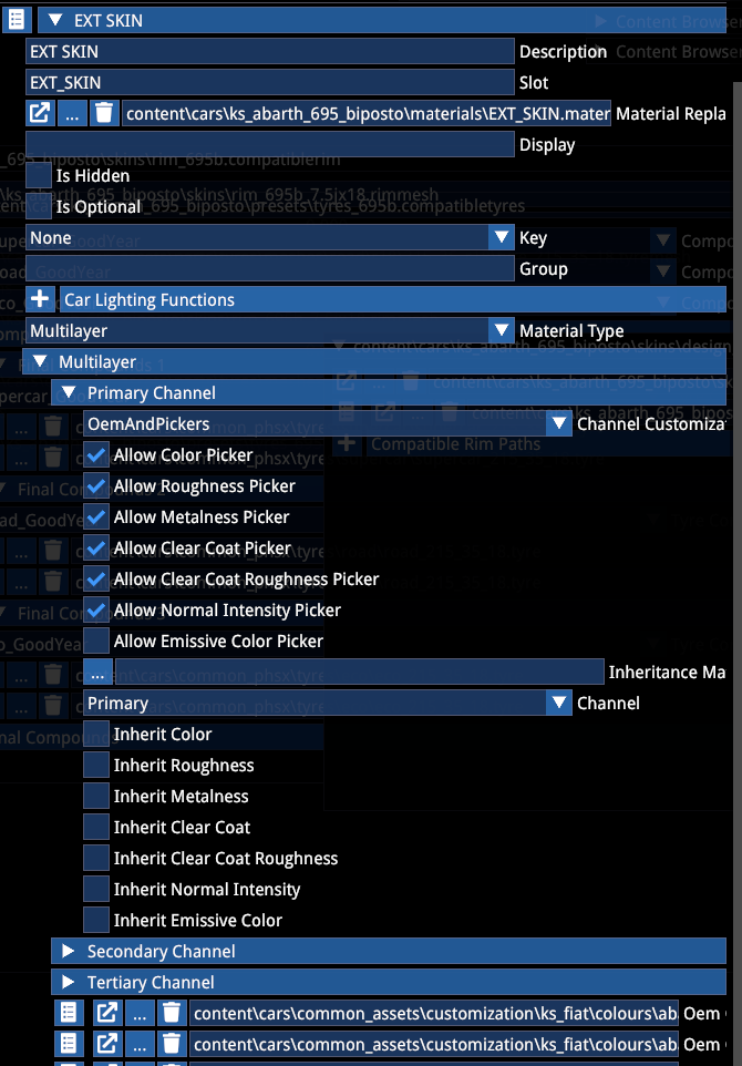
And here you can see how the cockpit carpaint material is set to inherit whatever is set for the SKIN material, including colour, all PBR properties and flake intensity (normal intensity):
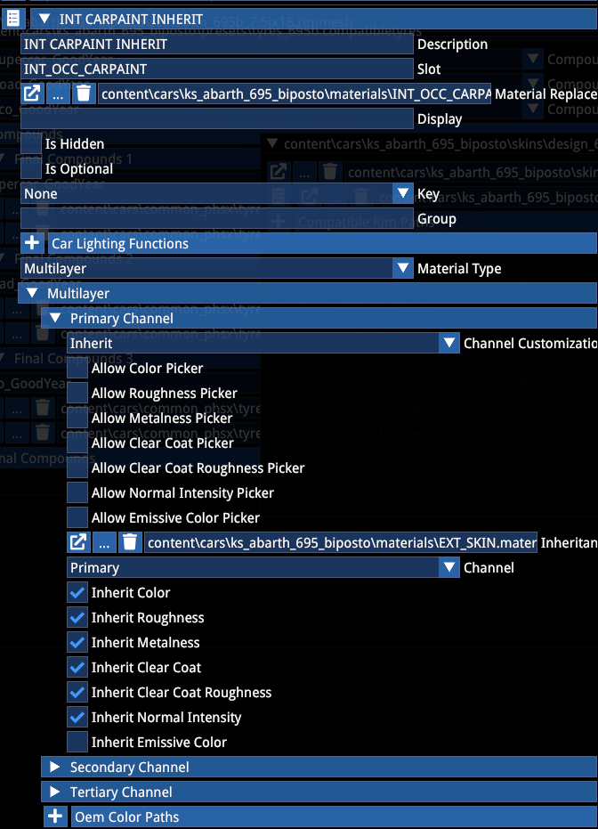
When only OEM is selected, the free picker choice is not available in-game. You can also limit which material properties are involved in the picker customization and inheritance, for example when an inheriting material is supposed to stay matte at all times and only inherit the colour, you can untick the properties that would inherit the glossiness and only tick the colour.
Besides colour changes, material definitions can include (and also combine) Optional items. In this case the material becomes switchable. Note that it can still have colour customization additionally.
The Key dropdown allows you to group multiple optional items to toggle together. A single design can use up to 10 groups (A to G):
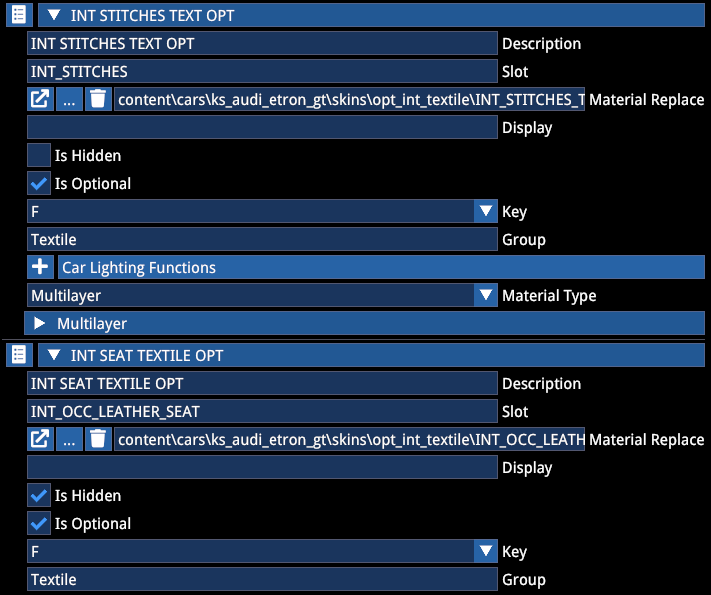
The isHidden option hides the material from being shown in the UI, so a group can appear under a single option in the game.
The Group entry is optional and arbitrary, it allows you to define different customization options to be subcategorized by the UI for less clutter.
The UI will show items in the following sequence for bodywork and rim materials:
Exterior/Interior -> (Group) -> Item
Rim -> Item
The rim's design files are based on the same design logic of colours vs inheritance and options:
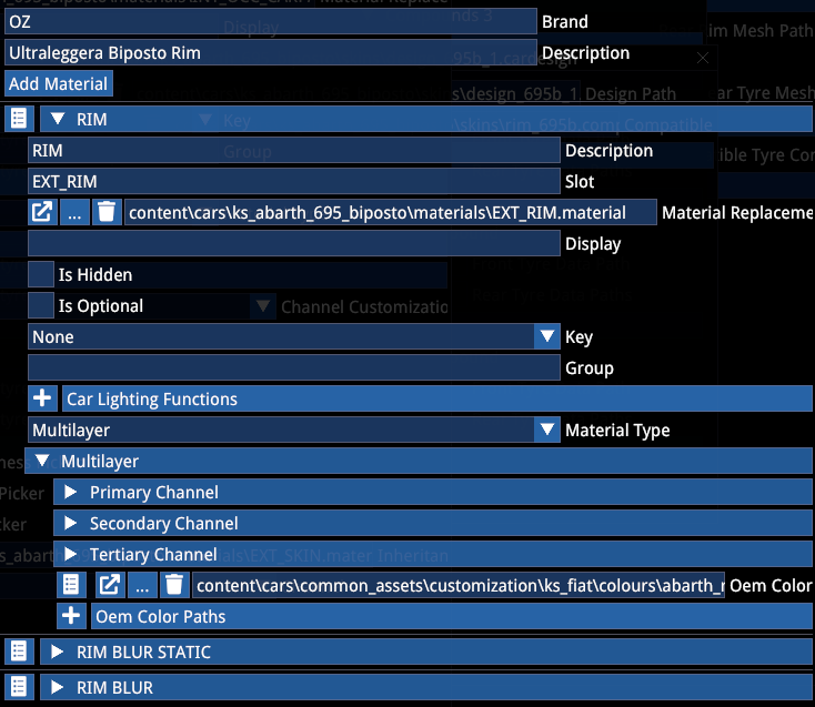
RIMMESH
RimMesh files are used to match rim meshes with their metadata and tyre compatibility. They contain the pair of rim meshes (both for static and blurred) for a pair of rims, and this is where the available design files can be listed, too.
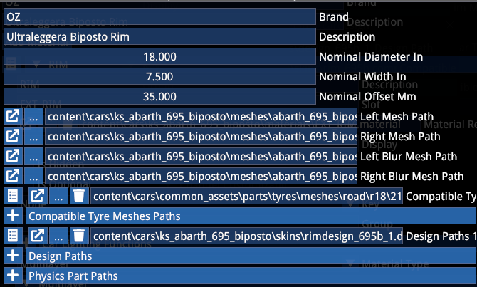
WARNING
If the car has different dimension wheels front and rear, it will require two separate rimmesh files! In this case the CompatibleRim file has to reference the correct pair for front and rear.
The CompatibleTyre field allows you to pair all compatible tyre dimensions for that rim. It can include multiple entries.
In the CompatibleRim file however, only one tyre dimension per rim can be defined.
If you want to pair the same rim with multiple tyre dimensions to the same car, you must create a CompatibleRim file for each combination! This is rare and we never actually came across this scenario (yet).
TYREMESH
TyreMesh file is a file that pairs a tyre mesh with its metadata, so that it can be referenced in the RimMesh and also the CompatibleRim files.
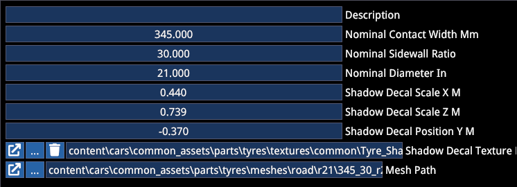
It defines nominal dimensions and the scale and position of the tyre shadow decal.
The correct position of the tyre shadow decal is:
| Property | Description |
|---|---|
| Scale X | Depends on how wide the mesh is (rule of thumb: contact width × 1.5 / 1000) |
| Scale Z | Length of the shadow = total diameter of the tyre |
| Position Y | How far down the decal should be placed from the hub level = tyre radius |
Use a website such as the Tyre Size Calculator to calculate the correct values.
7. PARTS
Parts customization allows you to add or replace parts on the car, either with cosmetic or physical implications.
The parts pipeline involves the following file referencing sequence:
Mesh file -> CarPart -> CompatiblePart
Data file -> TuningPart -> CarPart -> CompatiblePart
Note: a single CarPart can hold multiple TuningPart files but only one mesh.
TUNINGPART
TuningPart file is a container that assigns a type to data files, which allows them to be assignable in CarPart files.
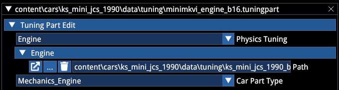
TuningPart files are only required when a part has physical properties. Cosmetic meshes do not require this.
For more information on physics data files, see the related documentation.
COMPATIBLEPART
This is a container that pairs a part to its car-specific installation data. Note that one part can be installed on multiple cars, but each installation requires its own CompatiblePart file!
This file can also define delta stance data when the part alters the showroom look (such as lowers suspension, adds camber etc.)
The CompatiblePart file includes the attachment rule, whether a part is supposed to be Additive or Replacement, and the bone it should attach to or replace. When Replacement is set, the part will replace the entire hierarchy under the specified bone.
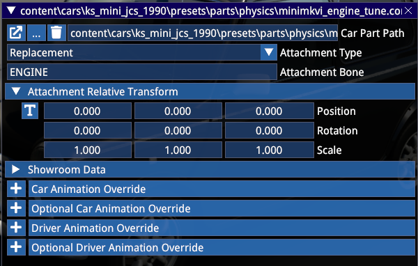
The Showroom Data section allows delta transformation to be applied on the car's showroom stance (e.g. when a suspension part alters the camber or ride height). These values are additive to the Showroom Data defined in the car Actor.
The Animation overrides allow for additional or replacement animations to be defined when the part is installed, such as when a steering wheel has a different diameter or position from the default wheel, and requires its own set of driver animations.
The Driver Animation Override allows you to set up the override animations the same way as it is done via the car Actor.
CARPART
Carpart files are the key components of part customization and they can hold graphical, physical and combined elements with metadata and additions or modifications to the car's existing scripts (display, leds, exhaust emitters etc.)
An example with an engine part that contains a mesh, audio files and physics files:
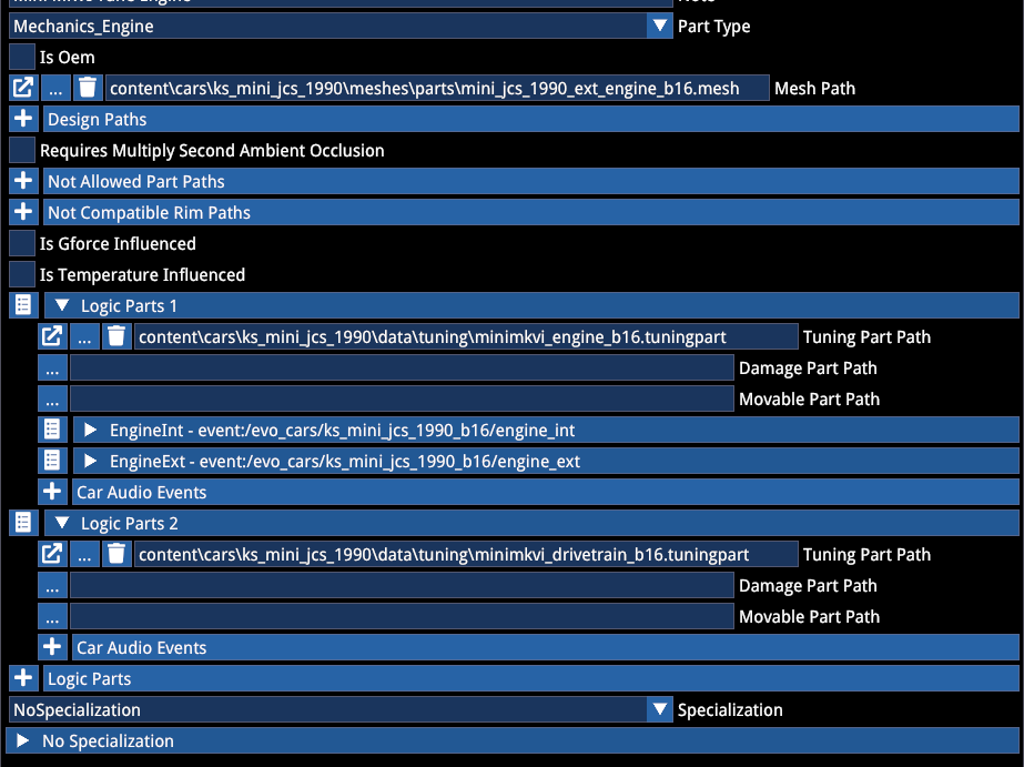
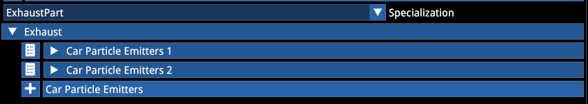
Another example with an exhaust part that contains modified exhaust emitter positions:
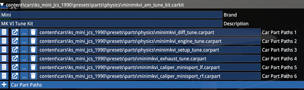
KITS
Kits can be used to group several files into a single entity. When parts are defined in a Kit, they toggle together and they only show up as a single item in the in-game parts selection (instead of each item being listed).
Kits operate on the CarPart level, meaning that it requires the CarParts to be listed in an array inside.
NOTE
Kits do not replace the necessity to create a CompatiblePart file for each CarPart!
Kits are useful when you do not want to clutter the parts list with a multitude of parts that otherwise are intended to be selected together.
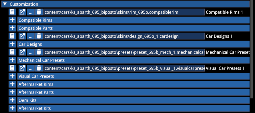
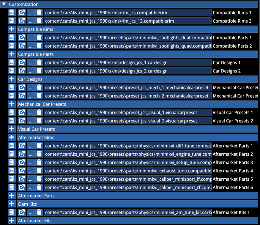
Assignment of customization and part files in the car Actor. OEM and Aftermarket sections can be used for differentiation in the UI:
PARTS COMPATIBILITY
The mechanical preset can prescribe that a part:
- Is installed by default
- Is forced installed by default (not removable)
- Is incompatible with that preset and cannot be installed
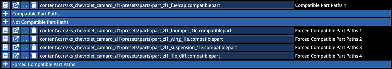
In this example of the 1LE variant of the ZL1, the fuel cap is installed but is removable via customization and the 1LE-specific parts are forced installed and cannot be removed.
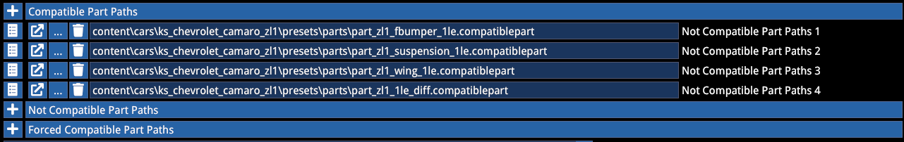
In this example of the base ZL1, the 1LE parts are not installable and the car has its default configuration (no added parts installed by default).
Incompatibility between parts and between parts and rims can be set up via the Parts file:
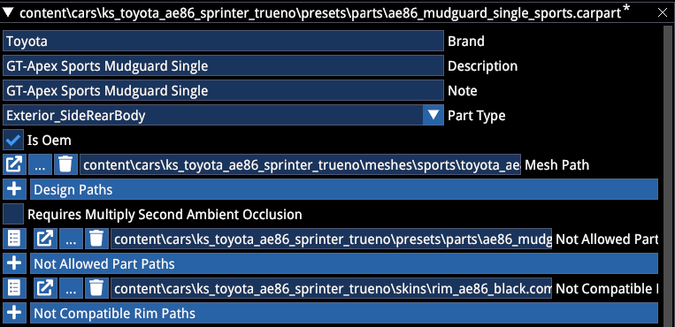
In this example above the GT Apex Sport Mudguard has an incompatibility specification with another Mudguard part and a specific rim.
8. INSTRUMENTATION
Due to the vast amount of possible combinations and setup possibilities, this guide will not go into too much detail on the scripting. It is recommended to study and play with the scripts included in the sample mod.
LIGHTS
The Main Lights section of the lights script defines the 3 main stages (ignition stage, low beam stage and high beam stage). The number of stages is hardcoded and cannot be changed.
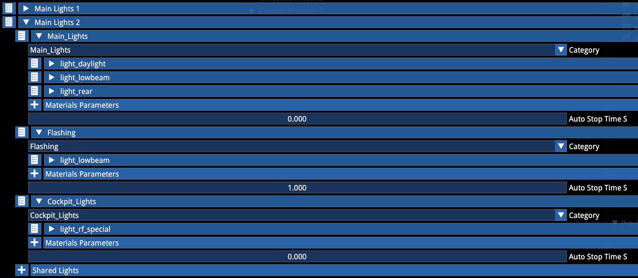
Only include functions here that change with the different stages. Minimize duplication to avoid confusion and mismatching values.
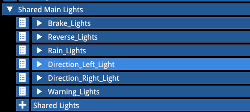
Use the Shared Main Lights section to define functions that are shared among the different stages:
The Pit Limiter section should be self explanatory.
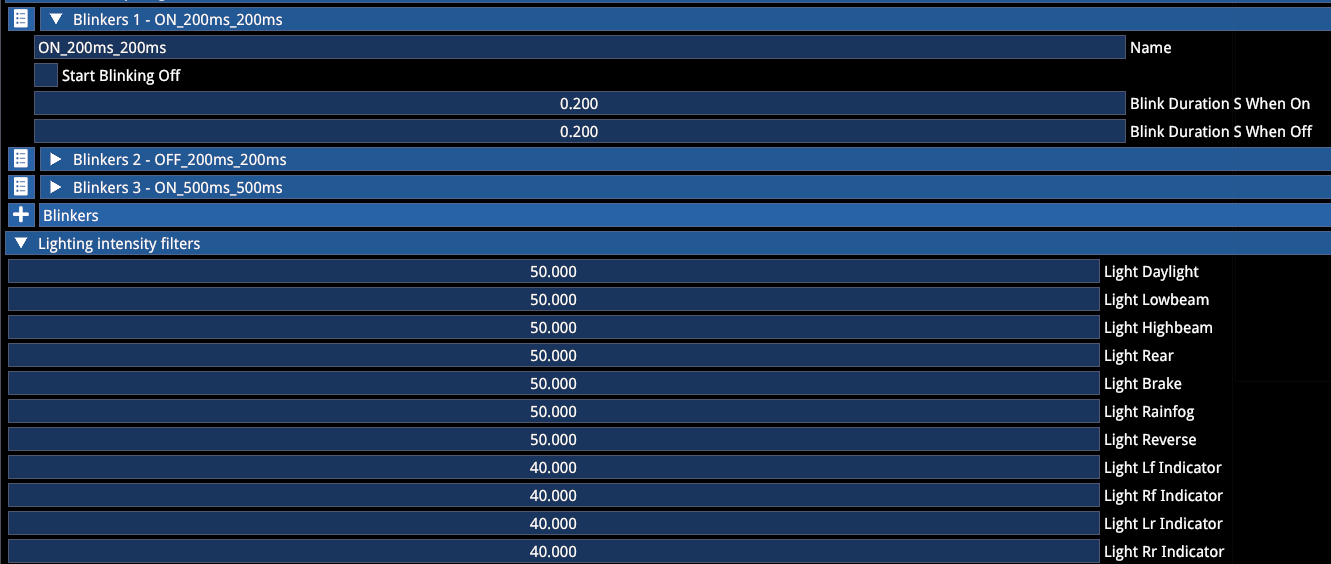
Blinker scripts can be set up to be referenced in the different blinking functions (such as indicators, flasher or pit limiter lights).
The Intensity Filter section allows you to set up a delay to how rapidly the light engages. Old-school lights should use lower values, while 0 is instantaneous.
When scaling the main light stages, make sure the high beam emitter value is 1.0 and you scale it downwards.
NOTE
Abusing emitter intensity can have severe performance implications!
Recommended emitter intensity:
| Light Stage | Emitter Intensity |
|---|---|
| Daylight | 0.03 |
| Low beam | 0.3 |
| High beam | 1.0 |
Recommended emissive values (clear glass or no glass):
| Light Stage | Emissive Value |
|---|---|
| Daylights | 1.0 |
| Low beam | 8.0 |
| High beam | 20.0 |
Rule of thumb requires these values to be quadrupled when using refracting glass. Make sure you don't overdo the glass emissives so that you can still see the source behind. Mix the two effects to taste.
You can use the luminance debug view to help with visualizing this.
LEDS
LEDs scripting allows LEDs to toggle with light stages and specific functions. The Led enum corresponds with the function mask gradient value (explained in the Texture section above).
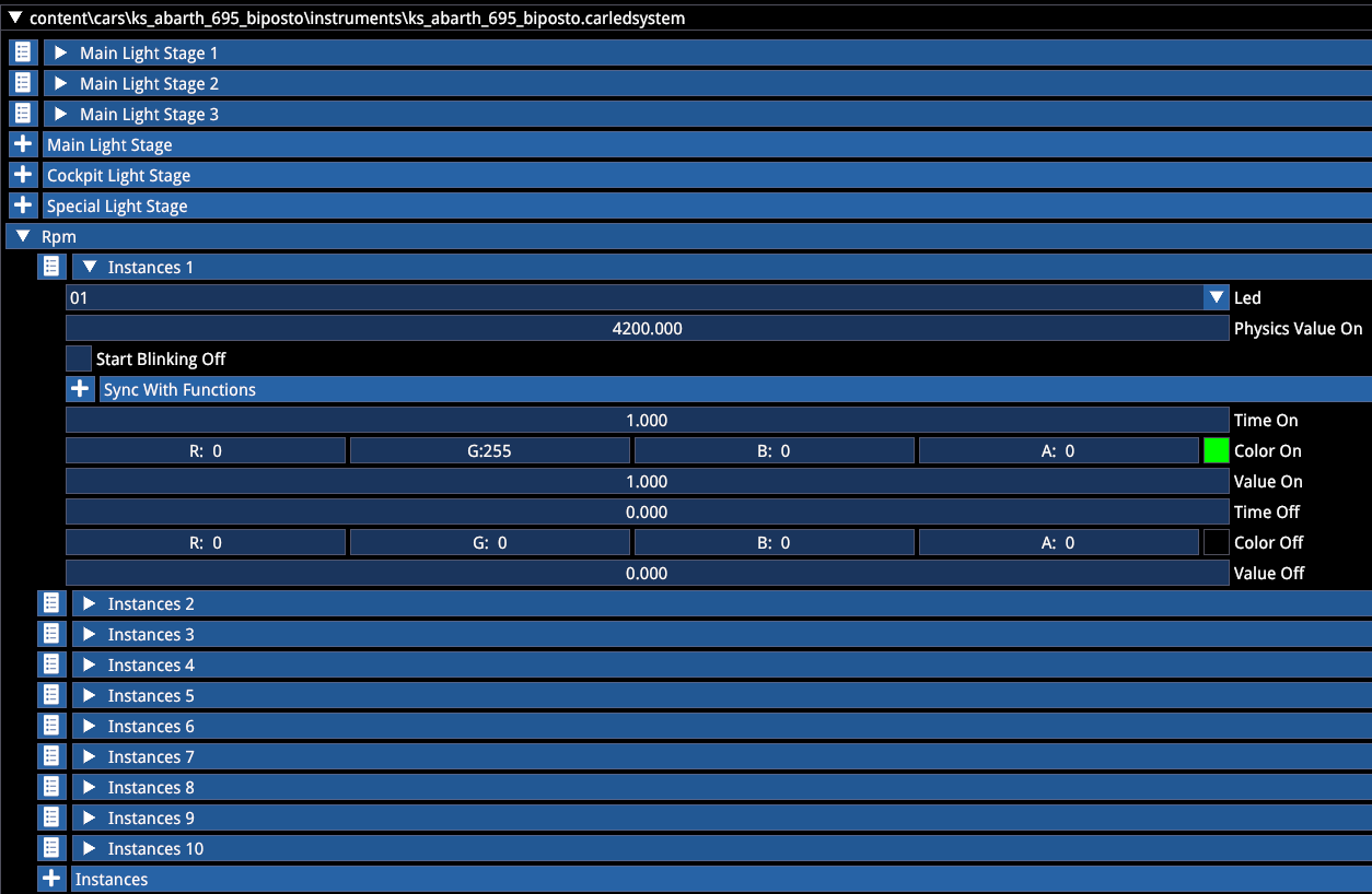
You have the ability to use the emissive texture to set the colour, in which case the script should multiply with a white colour, or use a greyscale emissive and change the colour via the script. For example for racing LEDs it is recommended to use the latter, while for warning symbols on dashes it is recommended to use the former.
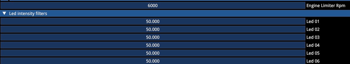
Similarly to lights, LEDs can also be filtered to have a more gradual glow up.
Recommended LED values:
| Type | Value |
|---|---|
| Racing LEDs | 1.0 |
| Warning symbols | 0.3 |
| Modern LED backlighting | 0.1 |
| Classic gauge cluster backlighting | 0.05 |
ANALOGUE
Analogue instrument scripting assigns a function to a lookup table, defining the attachment bone and the axis origin that the needle is rotated around (usually Z if the fbx is set up correctly).
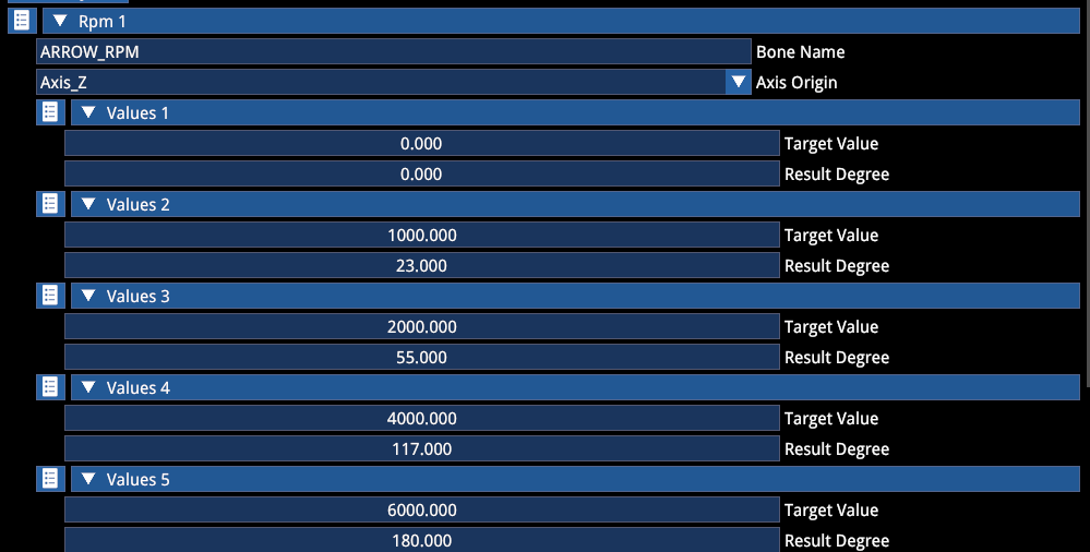
Filtering (for more weighted movement) and oscillation can be added when necessary:
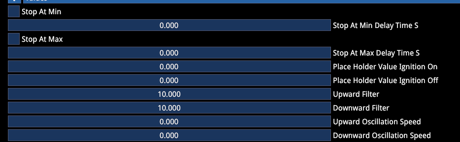
10.0 is a good starting point for a weighted feel.
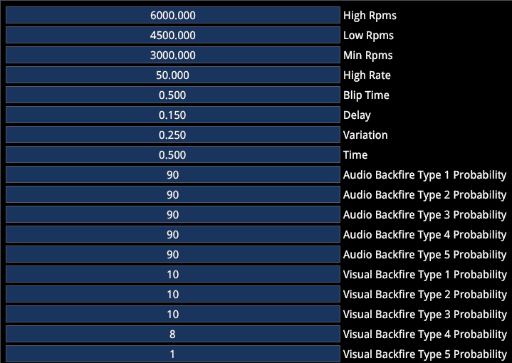
EXHAUST BACKFIRE
The exhaust backfire script includes the backfire logic for audio as well as the visual particles.
The visual probability is an additional multiplier over the audio probability. Use relatively low values, since the triggers can often repeat in quick succession.
A total of 5 backfire scenarios can be set up, each with its own probability and particle emitter (see the Particle Emitters section).
WIPER
The Wiper script is a simple script that allows you to set up the different wiper stages and timing, as well as the dynamic effects, such as vibration and g-force-induced transformation.
Official content uses a shared script, which looks like the following:
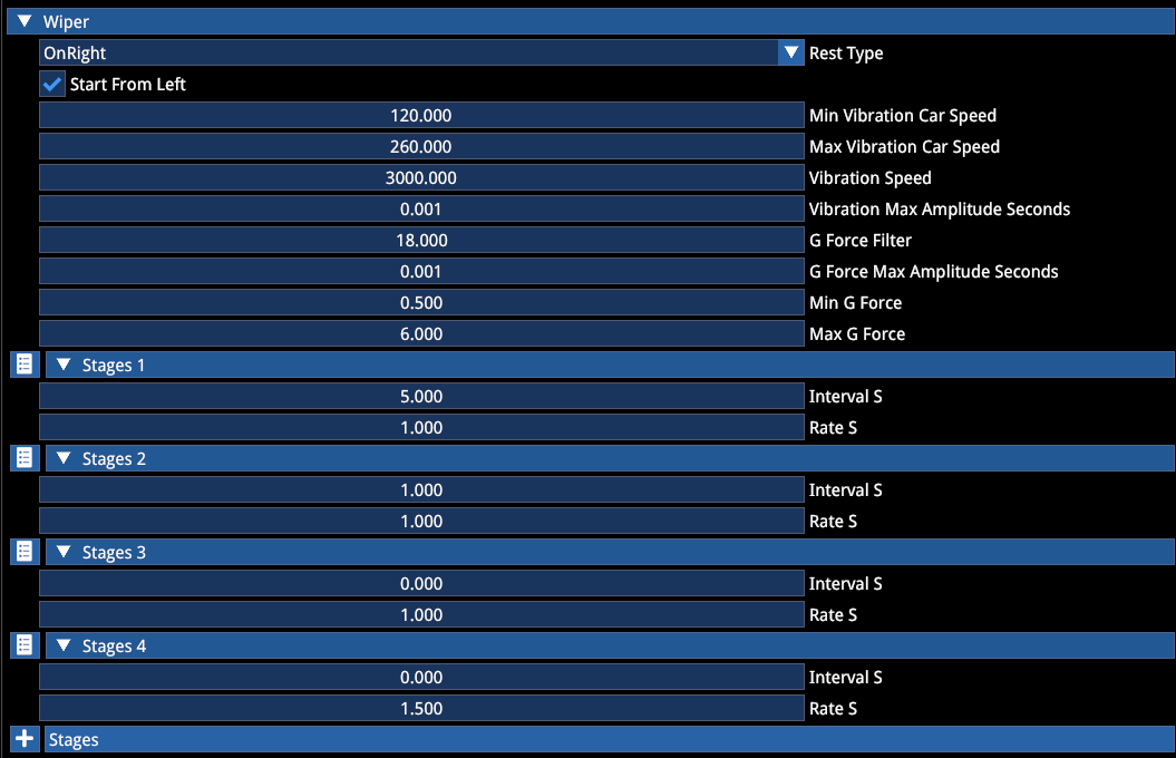
Note that specifying fewer stages might result in an incorrect behavior of the automatic wiper assist.
This script also includes the oscillation and g-force logic for the wiper.
The Max Amplitude seconds for both entries refer to the animation loop. Use very low values (if any).
Min and Max G Force values set the window from which the g-force influence starts taking effect.
9. FINALSTATE EDITOR
The finalstate editor's main purpose is to allow you to preview the final assembly of the car, with all functions and its customization logic, without being necessary to keep going back and forth between the editor and the game.
Contrary to AC1, where the editor was purely used for material editing, here almost all functions are watchable and debuggable through the finalstate editor.
Additionally, there are certain elements of the car that can only be generated through the finalstate editor. We will begin this section with those first and then move on to the sections that are focusing on preview/debug, rather than the creation part.
For the car to appear in the finalstate editor, it must have all meshes imported, materials assigned and filled with the correct shader type selected for functional shaders, the minimum customization hierarchy set up (see Customization section above), and the mod car data file filled with the name, actor and folder paths.
To access the editor, go to Tools -> Gameplay -> Car Finalstate Editor.
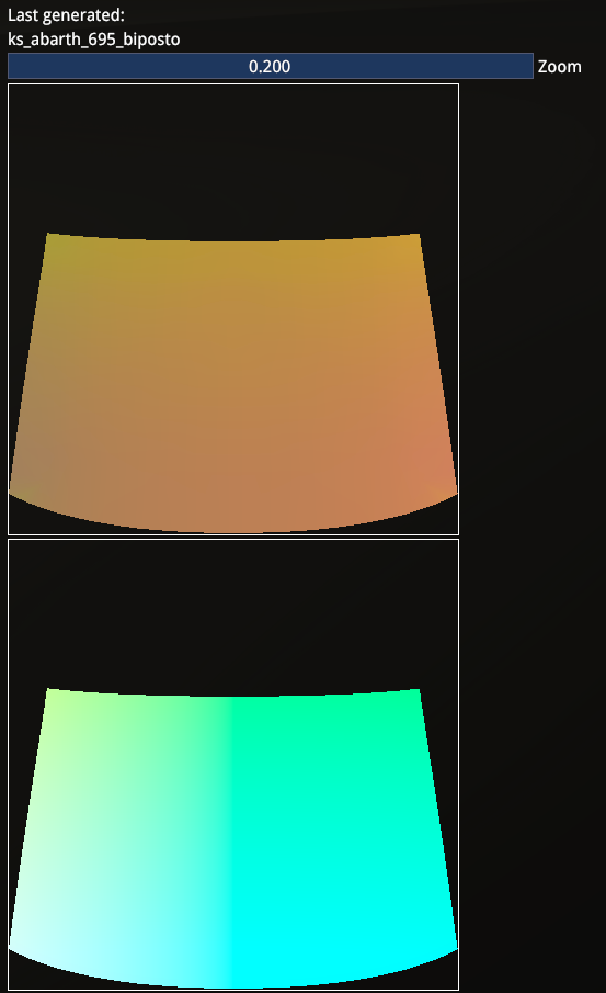
BAKING
Go to the Baking tab and press Bake Current Car. This will generate the world normal maps that are required for the windshield wiper effects to work correctly in the world space:
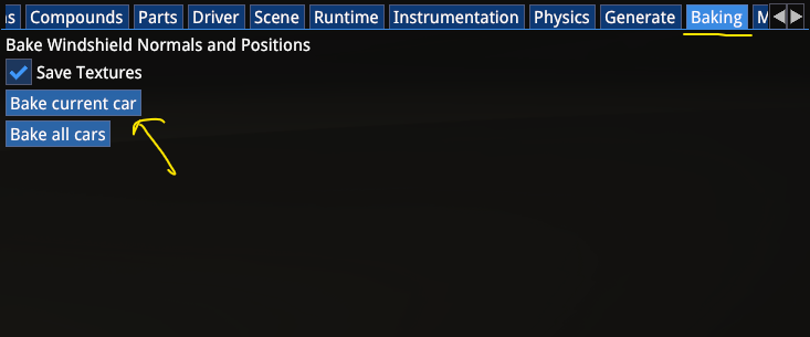
The generated textures will look like this and will be automatically saved after generation.
GENERATE
Another tab that is used to actually create assets is the Generate section.
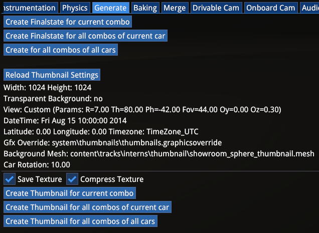
This allows the creation of UI thumbnails of each mechanical and visual preset combination and also the finalstate definitions for UI selection.
The difference between the buttons should be self-explanatory.
Keep Compress Texture enabled!
BODYWORK
The Bodywork tab shows the exterior and interior customization options. You can select between the Mechanical Presets, the corresponding Visual Presets and then each customizable material underneath.
When a material has customizable colour selection, the colours are listed there as well:
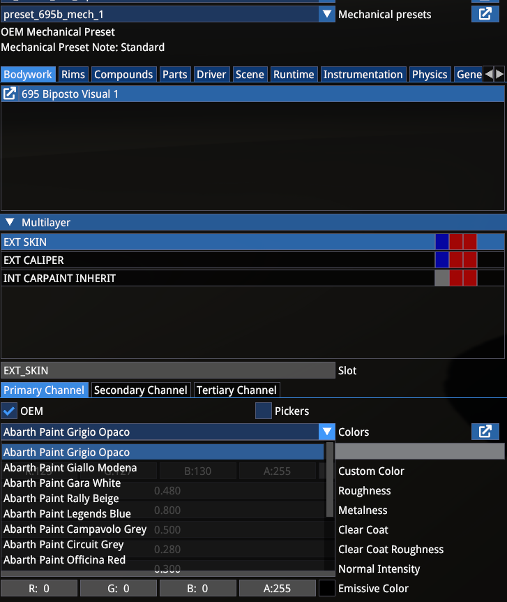
This is the primary place to test and debug your customization scripts and user-facing presets and their configurations.
RIMS
The Rims section shows the rim-specific customization, since the rims constitute their own entity inside the car customization, parallel to the bodywork customization.
The first list includes the available rims, then the available design variants for each rim and then the customizable materials inside that design:
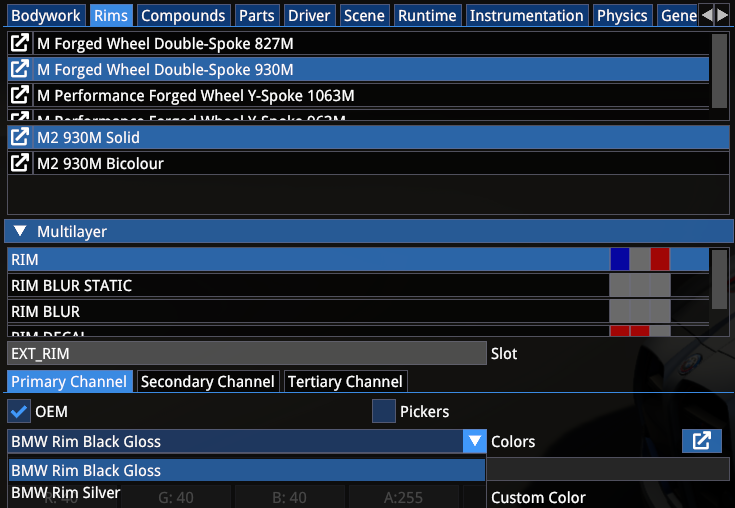
The above example shows 4 different rims and 2 design options for the selected rim, with the colour selection.
COMPOUNDS
Compounds tab shows the available tyre compounds graphics.
PARTS
Parts tab shows the available parts for the selected Mechanical Preset and their status and rules.
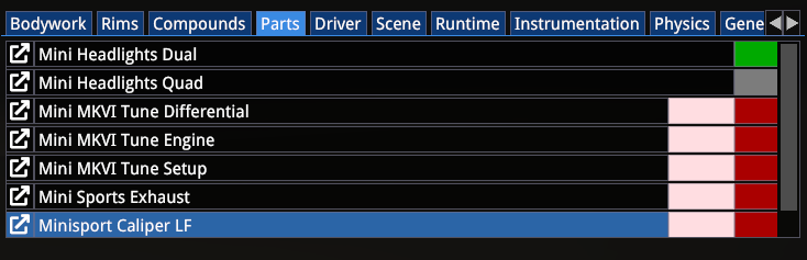
The pink box indicates a Kit (the items inside toggle together), while the grey box indicates the unavailability of the corresponding part with the current selection — in this case the Quad headlights being unavailable with the Dual headlights installed. Removing the Dual headlights will make the Quad headlights available for selection.
SCENE
The Scene tab allows for the rotation of the car model in the scene, and loading a background mesh.
RUNTIME
The Runtime tab is the primary place to debug car functionality. It is the tool to preview window and windscreen functions, damage and dirt functions, wheel functions, driver and car animations and rain functions.
Digital Display, Lights and Leds are shader-level debug tools — when instrumentation scripts are set up, their functionality should be checked via the Instrumentation tab (see later).
Since Digital Display use an external library, their functionality through the html scripts can only be checked inside the game.
Note that certain animations will also stop working correctly via the Runtime debug when the appropriate scripts have been set up, such as wiper animations.
Level of Detail section allows you to debug each LOD stage in combination with the car functions, so you can see animations and scripts work correctly also on lower LODs.
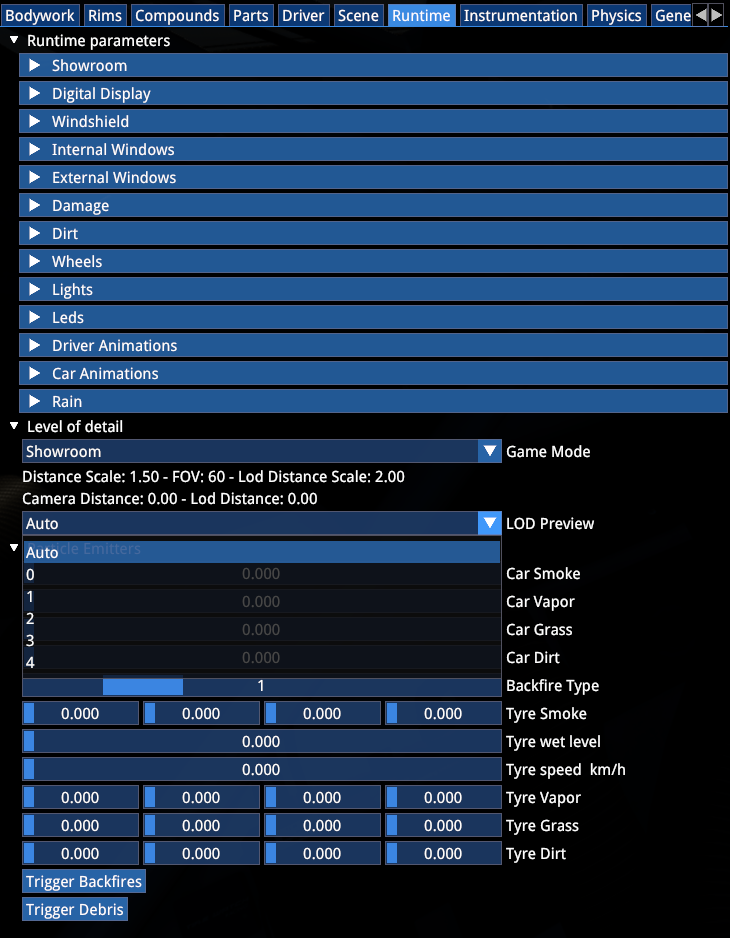
The Particle Emitters section allows you to see particle effects without having to launch the game.
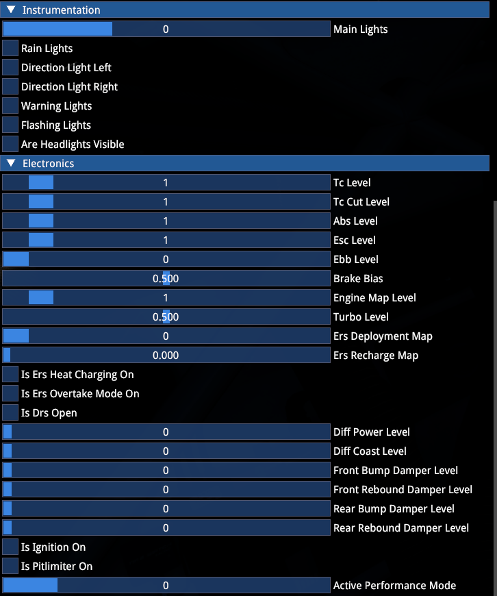
INSTRUMENTATION
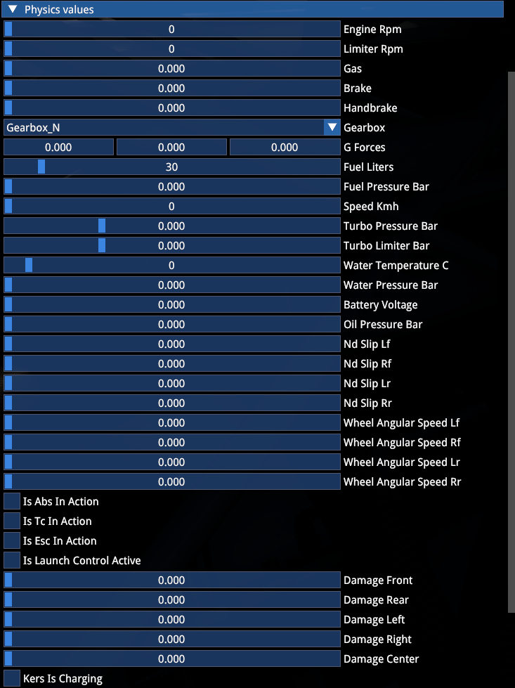
The Instrumentation tab is the primary place to preview car features in their functional context.
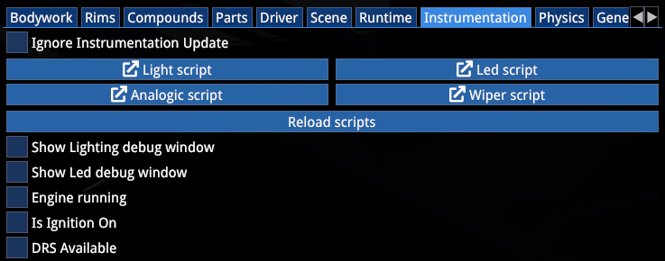
Here it is possible to apply car ignition and starter stages, the different lights stages and various physical properties and electronics levels to preview lights and leds and analogue instrumentation.
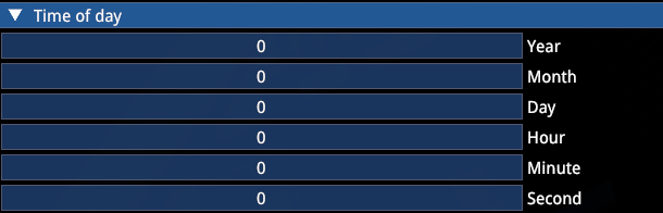
Time of Day section allows you to preview the functionality of analogue clocks:
DRIVABLE/ONBOARD CAMERAS
Drivable Cameras section allows you to preview and edit driving (F1) cameras and save the actor through the Finalstate Editor:
Onboard Cameras section does the same for the F6 cameras:
10. DEBUG TOOLS
This section will show some of the (mostly visual) debug tools that are accessible in the editor that should facilitate graphical work on your mod cars.
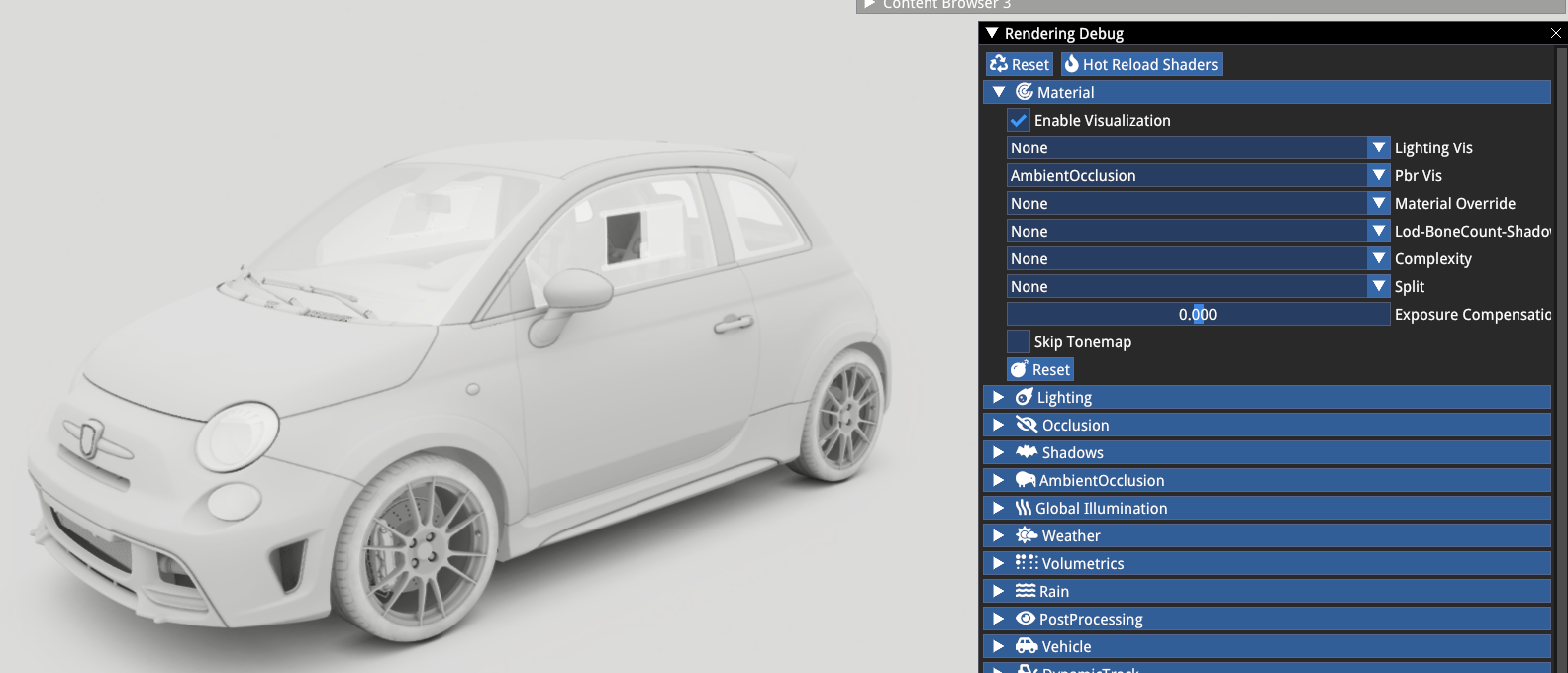
RENDERER DEBUG
Renderer Debug is accessible via Renderer -> Debug.
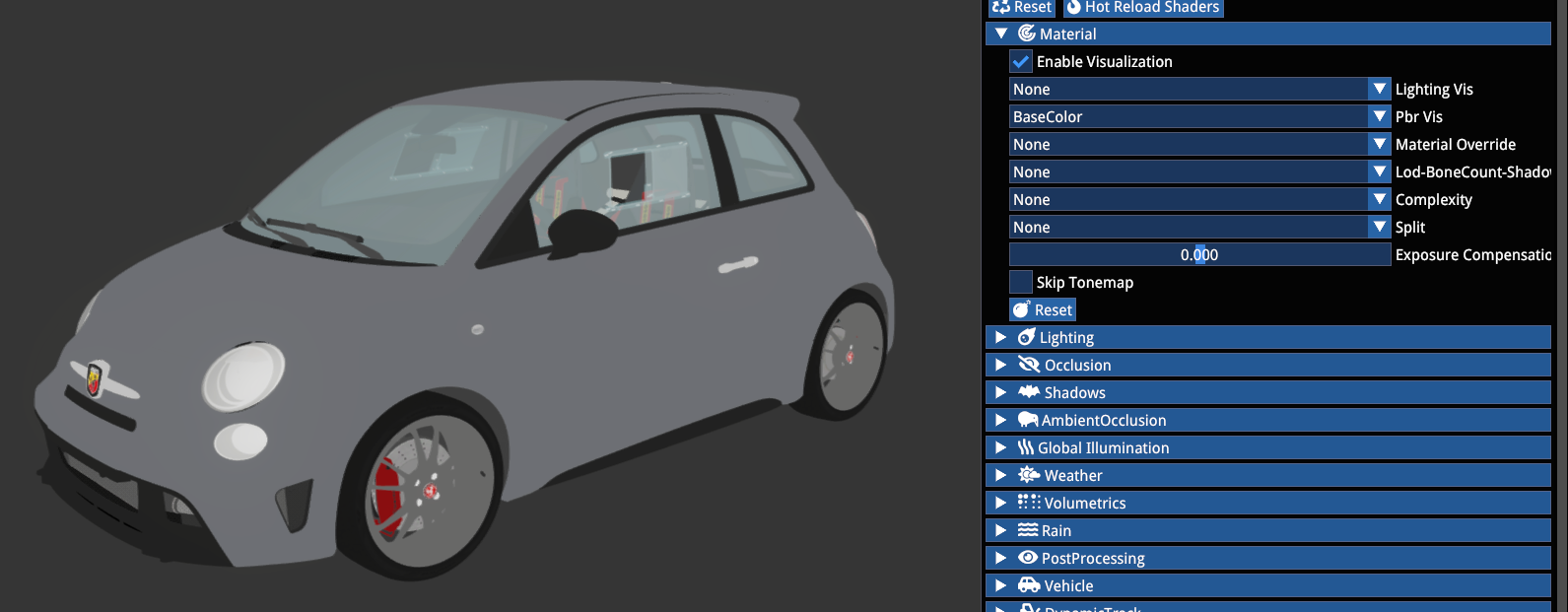
Its most relevant section is the Material tab, where PBR visualization helps us debug our material setup and ensure that our car is cohesive with realistic colour levels, consistent (and correct) ambient occlusion and PBR.
Ambient Occlusion:
Colour/Albedo:
VISUALIZATION
One of the necessary steps for correct lighting setup is to correctly define the cockpit probe capture position and size in the Actor.
For this we have to use the Debug -> Visualization window by typing in probe_cockpit_color and looking at the image.
Additionally, enable Show Reflection Probes in the Preview Options -> Scene -> Helper section.
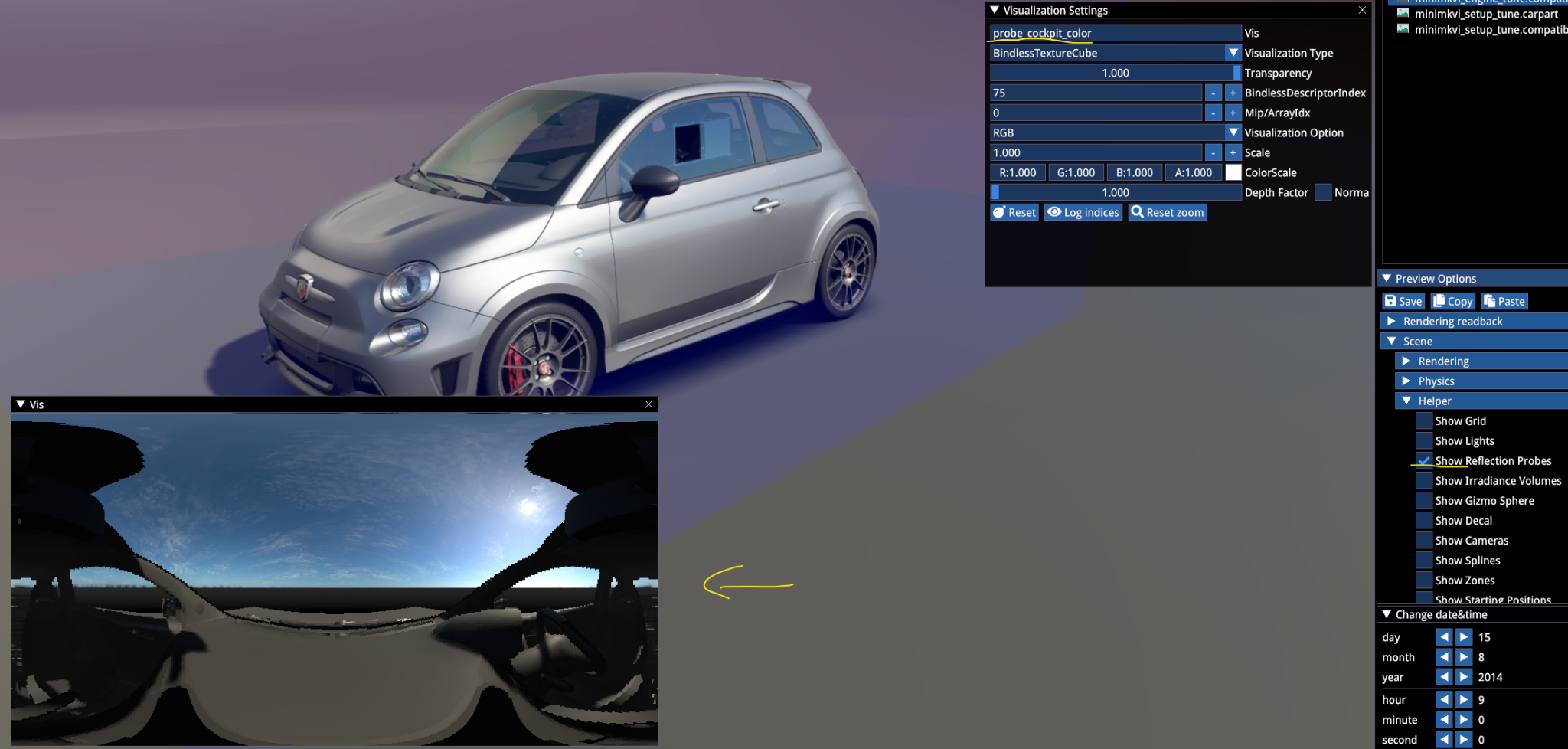
The probe position and dimensions should be set in the Actor's Cockpit Probe Transform section:
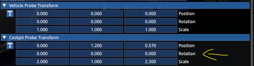
Move the position until the Vis window shows an image where the origin is roughly above the dash with the upper section of the window clear (the roof section must not close in).
The scale X should be large enough so that the doors are included also in open position (start from 2.0) and the scale Z should be large enough so that the entire cockpit mesh is included.
If the cockpit probe is too small, it will result in harsh lines of reflection boundaries on the interior mesh. If it is too large, it will add too much reflection information from the surroundings on interior materials.
If the probe is mispositioned (e.g. placed inside the dashboard), the reflections will be dark and dull even with correctly set up PBR materials.
DATE & TIME
The Date & Time menu allows you to set a specific date in the selected time zone and world coordinates.
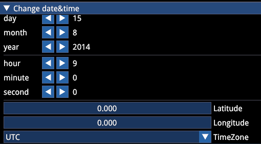
It provides you with the appropriate sun angle and direction for your selection.
PREVIEW OPTIONS
While it has been mentioned before briefly for certain debug features, let's go through the most important sections of the Preview Options menu.
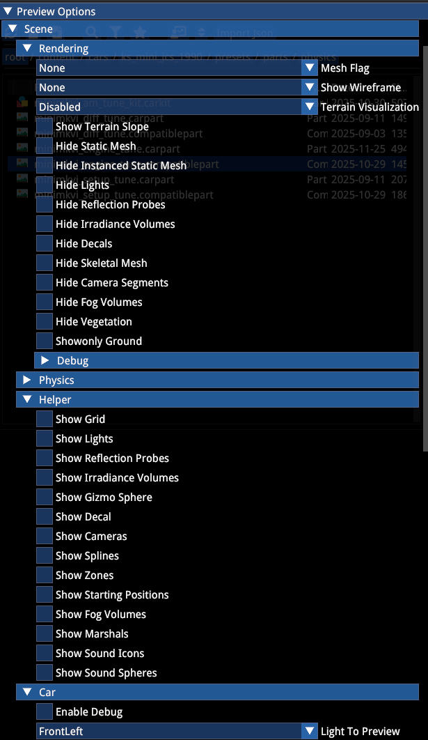
Scene menu contains debug options for the Rendering, visualization Helpers and Car light debug cones. The options should be self explanatory.
Some settings are related to environment work and general lighting debug, they can be ignored.
- Sky allows you to choose between the procedural sky (which reacts to time of day settings), or static sky, which is lit by a selected HDRI.
- Post processing allows you to choose from the game PP presets.
- Camera section allows you to change the FOV of the free editor camera.
EXPORT AND ENCRYPTION
A functional mod can be exported in two ways to be read by the game:
Copy the
mod_folderas is toSaved Games/ACE/mods/content/carsThis is recommended while you are still actively working on the project to check the mod in-game and go back and forth between editor and game.
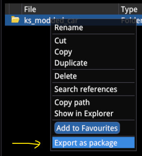
When ready to package up your mod, use the encrypt function of the editor to encrypt the
mod_folderinto a.kspkgfile.
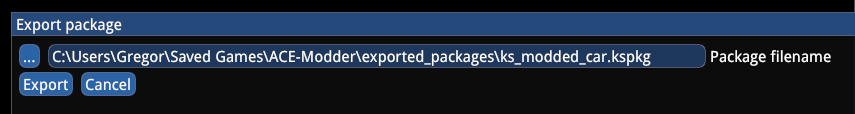
Copy the .kspkg file to Saved Games/ACE/mods/.
The sample mod includes both an open package for a reference project and an encrypted mod file.
KNOWN ISSUES, WIP & WORKAROUNDS
While during the general development part, the editor is known to be relatively stable when it comes to unexpected crashes, make sure you regularly save assets.
The finalstate editor will crash in the following situations to indicate a critical error in the asset:
- mesh assembly contains clashing bone names (same name for multiple bones)
- mesh assembly is missing a mandatory bone (such as
TYRE_,WHEEL_,DISC_etc.) - empty path in one of the files — make sure you do not add a new array item without filling it — finding the error can be quite frustrating as the log will not tell you where the empty reference is
- missing or wrong reference between the design file and the visual preset — such as the visual preset defining a default OEMColour file for a material that does not have that (or any) colour file in its array
- missing or wrong reference in the part pipeline
- when working in the finalstate editor, closing it and working in the mesh editor or material editor, and then opening the finalstate editor again, the editor can occasionally crash
Our recommendation is to start simple and expand from there — as a first step after the initial mesh and material setup, make sure you have a working finalstate preset with a single mechanical, single visual preset and a single set of wheels.
When adding parts, make sure you have a grasp of the whole pipeline before you start adding them in larger bulks.
References
- Kunos Simulazioni, AC EVO Car Modding Pipeline official documentation