AC EVO — Car Modding Pipeline: Physics
Changelog
- June 3 2026: V1
Foreword
The Car Editor is a work in progress tool and will remain so for a considerable period of time. Please check back regularly after every update if anything has changed. Being a constantly evolving tool, over time redundancies and dependencies have changed and will keep changing. You will find many fields that seem unintuitive at first glance or are redundant and relevant in another place or file. Overall a car can easily be 500 data points and an error in any of them or in any link or dependency can and will lead to crashes. Keep an eye on the log in these cases.
The physics engine is based on the Open Dynamics Engine. The main relevant information is that various distances are referencing the center of gravity.
To keep the documentation somewhat short, I'll skip past obvious fields.
Units
Unless mentioned otherwise the editor will use the metric system with SI base units. I.e. meters, kilograms, seconds, newtons and so on.
1. STRUCTURE
General
All relevant files for a car should be in the /carname/data/ folder, specifically the .car (Car Data) needs to be in there. All other files can be organized in a subfolder to your liking. They will be linked inside the .cardata. Once a file is linked, you can also move files to other places, the links will be updated automatically (the file receiving the updated link must be closed for that).
⚠️ Many places will use 0-based indexing. E.g. "TC Setting 1" will be referenced in the .carsetuplimits as "0".
⚠️ If you create a field under a dropdown and do not fill it, the game will find "NaN" and crash.
Files and links
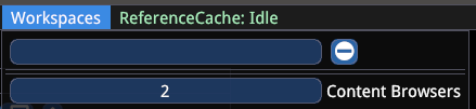
First create a content browser by increasing the number: Workspaces → Content Browsers
Known windows hotkeys do not work. The mouse is your friend.
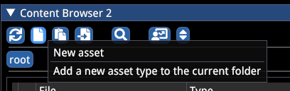
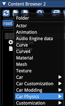
To create files go to:
- New Asset → Car Physics → choose respective parts
- You will also need New Asset → Curve (a lot of curves!)
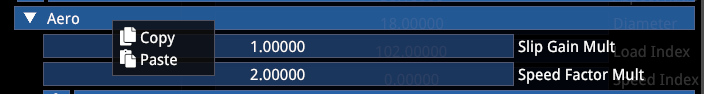
You can copy and paste entire sections of a file into the same section of another file.
Unfold a section, then right click → Copy and do the same in the target file.
You can drag and drop a file to a link, e.g. a .wing to the respective field in .cardata

2. PROCESS
Disclaimer
Save often. First for avoiding losing data during editor crashes, second because saving will ensure a change becomes effective when trying to gauge its impact. The editor runs the same physics as the game — very high and very low values will lead to issues. These are your #1 source of crashes.
Live Preview
For the physics to run the preview window needs to be open and unfolded and either the .car or .carsetup file needs to be opened. However, the physics can only run one instance, so the file you open first will be what you see. All values in the .carsetup will overwrite whatever is in other files.
⚠️ The
.carsetupis your ultimate "reality". The file selected in the preview is the one that's active from a simulation POV.

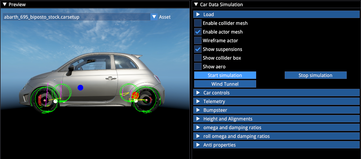
Opening either file will also open the "Car Data Simulation" window. Click "Start Simulation" to let the physics activate — you'll see tyre meshes and various spheres become visible.
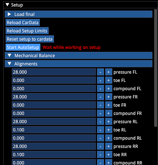
Opening .carsetup will also open the "Setup" window, akin to the in-game setup screen. "Start AutoSetup" triggers the "automagic": the car is placed on a flat plane, follows all values in the car setup, and suspension elements "converge" to match the current setup values ("Wait for working on setup").
This is the main difference between ACC/ACE and AC1 currently. The camber, ride height, toe (...) values you set remain true, the rest of the suspension needs to adapt (or "converge"). Future updates will change this: ride height will no longer be a direct selection but a passive value resulting from other changes, making the process less tedious.
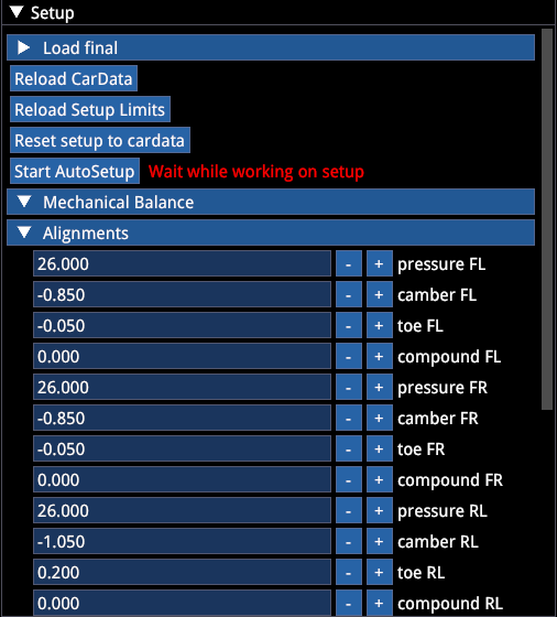
Make sure to let the setup "converge" once at the end of every editing session, so the car will reflect all the latest changes. E.g. changing the center of gravity or fuel tank position, or just making a 100g adjustment to the car weight requires the car setup to be recalculated to be fully correct. But don't be surprised if recalculating the setup produces slightly different values each time even when you haven't changed anything, due to floating point precision.
- If you modified cardata while the car setup is open and want to see the impact: → "Reload CarData"
- If you modified
.carsetuplimits(the allowed adjustable ranges) and want to see them reflected immediately: → "Reload Setup Limits" - Ideally don't click "Reset Setup to cardata", this resets the setup to whatever is stored in other files, which can be messy if you don't maintain them
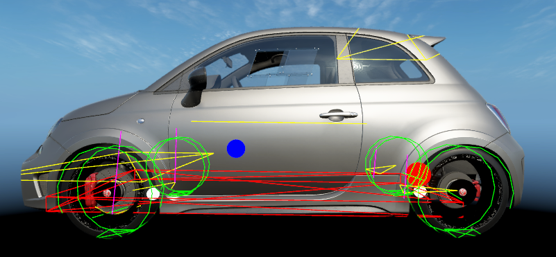
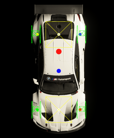
Visualization
| Element | Description |
|---|---|
| Blue sphere | Center of Gravity |
| Red sphere | Fuel tank center |
| White sphere | Ride height pickup points (setting 100mm ride height means this sphere's center is 100mm from the ground) |
| Yellow rods | Suspension wishbones or similar |
| Purple | Strut |
| Yellow planes | Wing surfaces (includes size and pressure center) |
| Red | Floor colliders (only the bottom plane is effective) |
| Green circles | Tyres |
Cars with an aero map will have additional green, yellow, blue, and red spheres representing the aero height measurement points.
File Overview
| File | Description |
|---|---|
.car | Main file, contains links to all other car parts |
.coilover | Front and rear dampers, contains bump stop data, damper speed thresholds, damper and bump stop simulation, progressive spring rate |
.suspension | Suspension geometry |
.drivetrain | Drive axle and differential data |
.gearbox | Gearbox type, ratios, behavior, shift-related assists |
.clutch | Clutch |
.engine | Type, power/coast curves, engine maps, throttle shape(s), turbo and controllers, Push2Pass, Launch Control (Start ECU), battery data |
.turbo | More detailed turbo definitions |
.brakesystem | Brake capacity, electronic brake bias controllers, automatic brake differential ("steer brake"), brake pads |
.brake | Brake pad and disc properties: friction, temperature, wear, etc. |
.tyre | Dimensions, tyre initialization, tyre model parameters (not adjustable) |
.wing | Aerodynamic components and related properties |
.surface3d | Ride height based aero map |
.carsetuplimits | Defines the allowed ranges for all .carsetup variables |
.carsetup | Defines the specific values for all adjustable and non-adjustable car components |
.curve | Multi-purpose lookup table file, used in various places and controllers to dynamically adjust all component properties |
.dampercurves | Wrapper containing multiple .curve files, contains damper speed → damper force LUTs, allows multi-knee racing dampers |
3. CAR DATA (.car file)
🔽 General
- Fuel is overwritten by the value in
.carsetup - Max Fuel is overwritten by the value in
.carsetuplimits - Efficiency if set to 0, it's hardcoded to 0.30 (30%)
- Body Box Size: Vehicle outer dimensions, used to calculate inertia
- Pickup front/rear height: Defines the ride height measurement points relative to the center of gravity
🔽 Suspensions
Cg (Center of gravity) Location: See the live CG position in "Car Data Simulation" → Suspension Debug section ("long distr."), including all other properties.
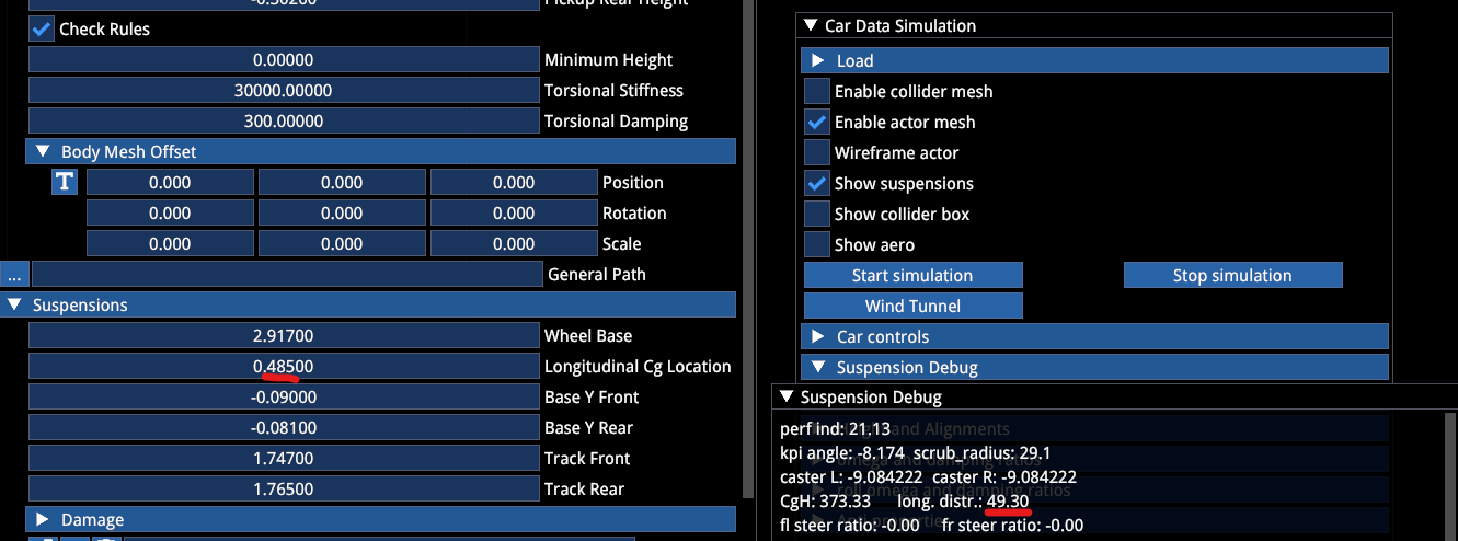
Base Y: Defines the vertical distance from wheel centers to the center of gravity. This is very important. All suspension geometry references the wheel center. Adjusting Base Y moves the CG up and down. You need to combine this with the ride height pickup points to find the correct CG height (cars with aero maps reference the aero pickup points for measuring ride height, not the ride height pickup points — you should align them with each other).
For example, if you have a race car where the CG height is 350mm at a ride height (floor to ground) of 50mm, given tyre size and pressure, you need to reproduce all these values and then adjust Base Y to achieve the correct CG height.
At the bottom of the .car file you'll find a tool that allows for easy and precise adjustments. Select a value on the slider (positive or negative) and click "move CG".
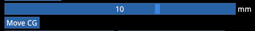
The whole process is iterative.
ARBs are not relevant in .car, they are overwritten by .carsetup. Unless you define ARB controllers that allow dynamic adjustment of ARB stiffness based on various other input values.
The ARB controller output is rate at the wheel in N/mm (▶️ see Controllers section for details)
Damper Controller
Allows custom active damper controllers where you can define multiple damper curves based on driving conditions. This is very powerful. To create a controller: expand the dropdown → right click → Create. All gains should be set to 1.0. Adjust and define all other properties to your liking. Once you have a usable active damper, you may be able to reuse it on other cars by using the "gain" value to increase or decrease the damping of the respective logic.
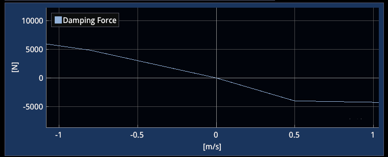
The damper controller output is pairs of damper speeds (m/s) and force (N) curves.
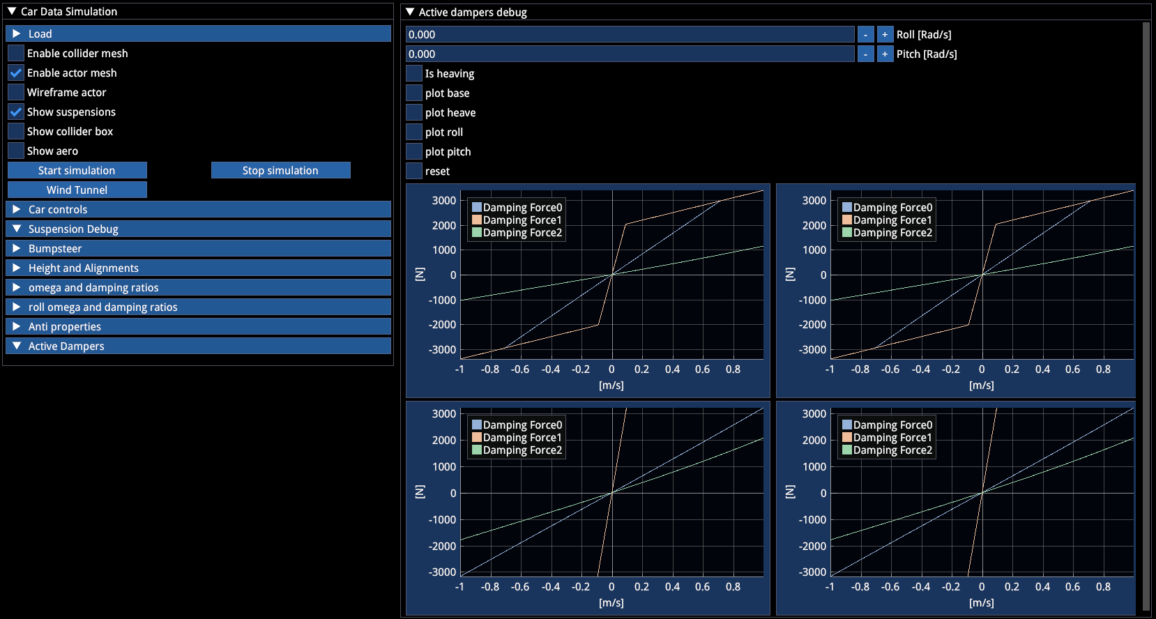
When active dampers are defined in the
.carfile, the "Car Data Simulation" panel will have an optional "Active Dampers" dropdown that will show "Active Damper Debug".
When active dampers are defined:
- Damper values in
.carsetupare ignored - Any damper properties in
.coiloverare also ignored
Activate "☑ Has Dampers Cockpit Setting" to enable in-car damper adjustments (hotkey or via MFD). The steps and limits for damper adjustments are defined in .carsetuplimits.
🔽 Steering System
This is dedicated to rear wheel steering vehicles. By defining a controller, you can make the rear wheels turn based on any and multiple available input variables.
The 4WS controller output represents the lateral displacement in meters applied to the rear steering arm attachment point.
- Positive value = toe-out
- Negative value = toe-in
There is a function that takes into account whether the toe arm is in front of or behind the wheel center — so you don't need to worry about that.
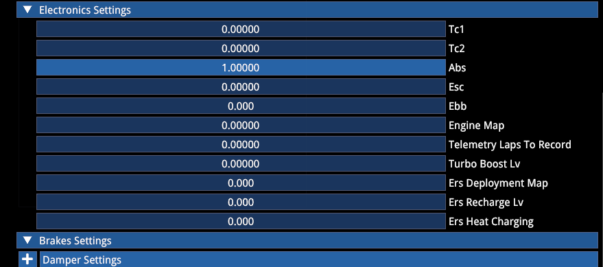
🔽 Electronics
Available levels also need to be defined in .carsetuplimits. To be able to turn off TC/ABS/ESC, Setting 1 needs to be defined as no intervention. Use 0-based indexing. TC1 = 0 in .carsetup and .carsetuplimits corresponds to "Setting 1" in the .car file.
TC (Traction Control)
Allows defining various TC parameters, responding to longitudinal (slip ratio) and lateral (slip angle) grip loss.
- TC1 has a variety of parameters including Engine Cut Level, Engine Cut Time, Slip Ratio intervention thresholds (min and max), Slip Angle intervention thresholds (min and max), and Ignition Cut (boolean)
- TC2 only adjusts the "Engine Cut Level" (i.e. the aggressiveness of intervention, lower = smoother, earlier), while all other parameters from TC1 are unaffected
ABS (Anti-lock Braking System)
Similar to TC. Recommended to not use a frequency higher than 40Hz, otherwise ABS becomes too perfect.
EDL (Electronic Differential Lock)
Not to be confused with ESC. Electronic Differential Lock acts as a braking input on the rear wheels in order to achieve differential locking effects during coast or power situations without the need for an LSD in the vehicle. Suitable for modern torque vectoring powertrains, though there are also other options in the .drivetrain file.
EDL, once activated in the
.carfile, cannot be turned off by the player.
ESP (Electronic Stability Program)
Electronic Stability Control. Allows defining more safety and stability oriented braking interventions, with multiple parameters.
🔽 Controls
| Parameter | Description |
|---|---|
| FF Mult | If the car's suspension (mainly caster, scrub radius, loading) results in weak FFB output, allows adjusting the baseline FFB output |
| Steer lock | Center → max lock angle (so the result is twice the total range) |
| Steer Ratio | Choose and adjust according to the real counterpart's design (needs to be negative if the steering arm is behind the wheel center) |
| Linear Steer Rod Ratio | Match steering wheel lock to tyre lock as needed |
| Steer Assist | Adjusts the linearity of steering input (1 = linear) |
🔽 Box Colliders
Defines the collision floor box for the car. Usually one is enough. Only potentially needed when the floor gradient changes sharply. Can be pitched, which is useful for cars with built-in rake.
Box colliders are computationally intensive.
🔽 Aero
Slipstream values currently only affect the shape of the slipstream "cone" available behind the car, not how much slipstream it receives. Recommended to keep defaults.
| Parameter | Default | Description |
|---|---|---|
| Slip Gain Mult | 1 | Slipstream gain multiplier |
| Speed Factor Mult | 2 | Speed factor multiplier |
⚠️ Positive lift is downforce (we're breaking with convention here). Positive drag is… drag.
Downforces
If you want to use a ride height based aero map, you want to have 4 corners of the car defined:
- 1 = LF (Left Front)
- 2 = RF (Right Front)
- 3 = LR (Left Rear)
- 4 = RR (Right Rear)
The CL and CD values are defined in the front and rear lift and drag surface3d file.
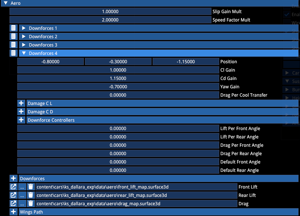
The placement of the Downforces 1–4 on the car will be used by the Setup as a ride height reference point. In the surface3d map, define the actual total CL/CD values you want the axle to produce. The code automatically splits it in half for the corners of the car. The longitudinal positioning of the downforce points influences the aero balance (logically).
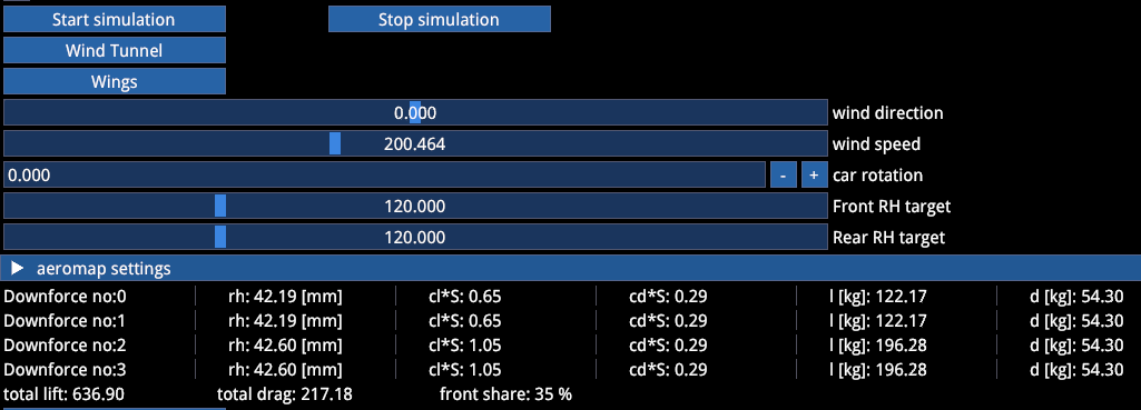
To see the realtime impact: "Car Data Simulation" → Start Simulation → Wind Tunnel → Wings → add some speed
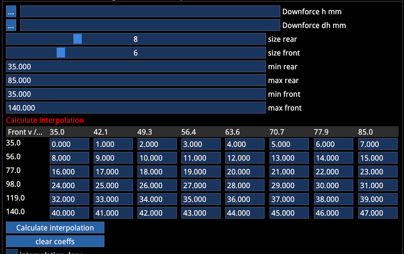
Example configuration:
- Size rear/front: defines the resolution of the table
- min/max rear/front: defines the range of the map
- Both together define the stepping
After entering values or importing a map hit "Calculate Interpolation" and save.
Debug: Click "🔽 Interp Map" to open the aero map visualization.
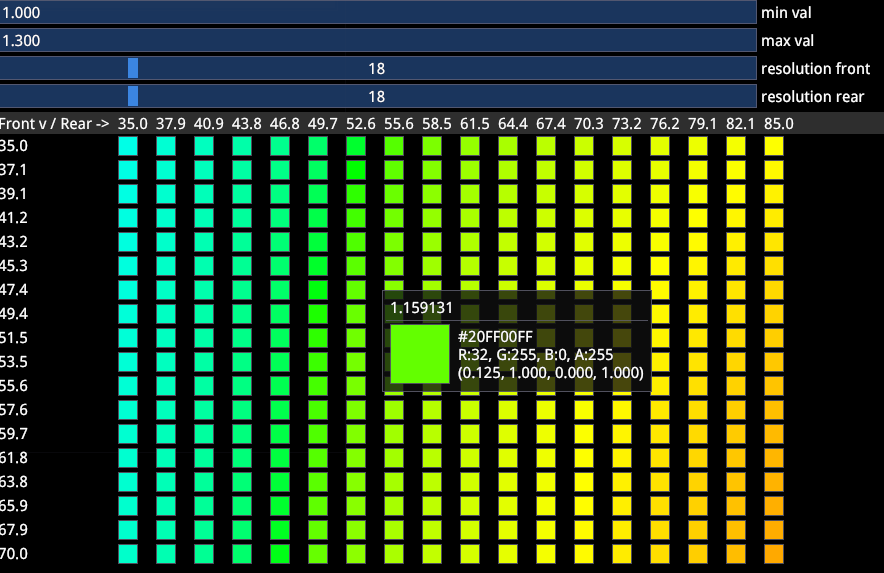
Realtime: "Car Data Simulation" → Start Simulation → Wind Tunnel → Wings → add some speed
CL and CD Gain: Allow for easy scaling of the entire map.
Yaw Gain: Can be used to increase or decrease downforce per axle with yaw. This becomes noticeable for values of 5–10.
Example: 5° yaw angle would result in ~9% downforce loss if Yaw Gain is -1.0.
Drag per cool transfer: Allows drag scaling with brake ducts (not yet implemented).
Aero Damage
Adjustable for both Drag and downforce.
Downforce 1 (front left) having the following values defines the damage sensitivity of that element to:
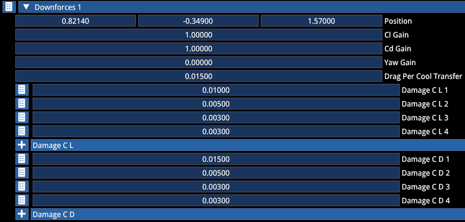
| Value | Collision Type |
|---|---|
| 1 | Front impact |
| 2 | Rear impact |
| 3 | Left impact |
| 4 | Right impact |
Lift/Drag per angle: Adds/removes downforce or drag with wing adjustment in the carsetup.
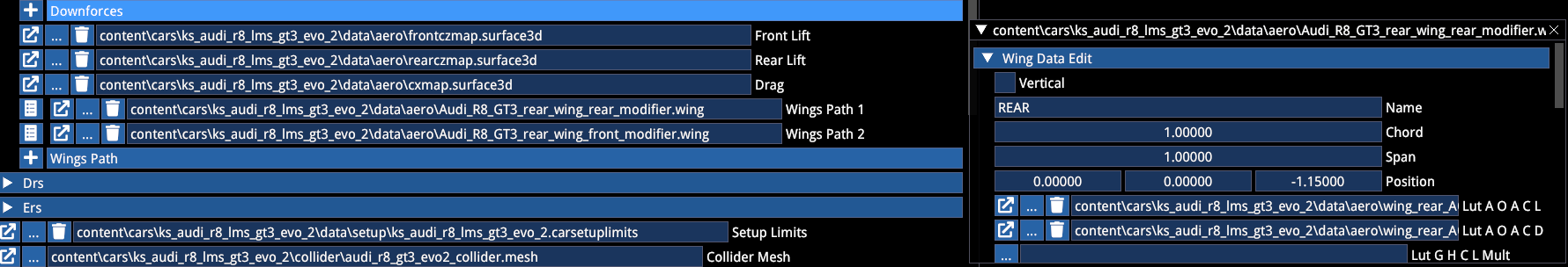
For GT cars we currently use a method that uses separate wing elements that add/reduce lift/drag to/from the baseline aero map. For that, place two wings (one over the front axle and one over the rear axle) both with the name "REAR". This hooks both wings up to the rear wing adjustment in the .carsetup regardless of where they are on the car. This allows for non-linear wing impact on aerodynamics via wing-specific lookup tables.
Individual Wings work along the same logic:
- AOA: Defines CL based on angle of attack
- G H C L Mult: Applies a ride height based multiplier to the AOA derived CL/CD values (akin to AC1)
Individual aero element names need to be as follows for them to be adjustable via the car setup:
FRONT
REAR
DIFFUSOR
BODY
DRS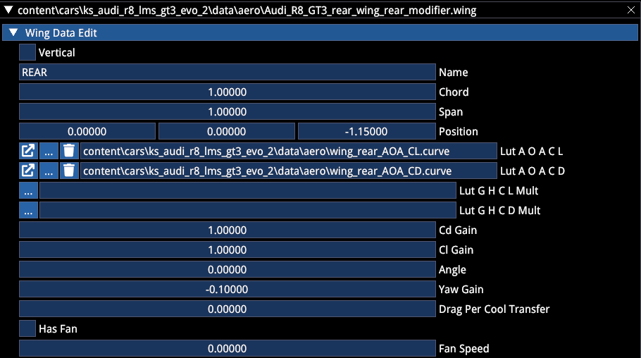
Wing controllers allow for active aero parts, both using aero map and individual wing elements. E.g. air brakes.
The output of a Wing controller is an angle in degrees.
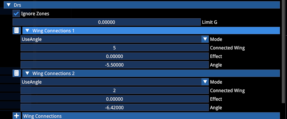
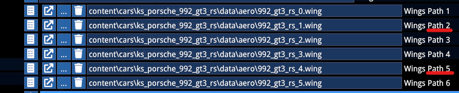
DRS
This allows you to hook up wings to the DRS function. In case of the 992 GT3 RS there is a front and rear wing affected when pressing the DRS button, targeting a specific angle (in the LUT) in order to achieve the desired CL and CD values and thus DRS effect.
You can alternatively use the "UseEffect" mode to use 0–1 scaling instead of a specific angle.
The "Connected Wing" ID stems from the Path ID in the .car file.
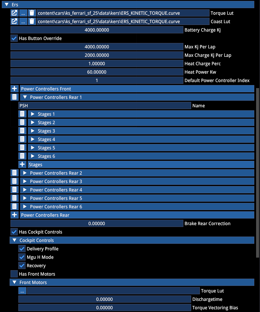
🔽 ERS (Energy Recovery System)
Allows for hybrid powertrains. Also allows defining limits based on for example F1 rulesets regarding the battery usage per lap.
- Torque LUT needs to be defined along the RPM of the ICE engine
- Power Controllers are the available ERS maps in the cockpit (if ☑ Has Cockpit Controls is active)
- ERS Maps can be tied to "Performance Modes" (see further below) and need to be allowed in the
.carsetuplimits. Counting is 0-based so "Power Controller Rear 1" is 0 for the Performance mode and.carsetuplimit, as well as the "Default Power Controller Index"
The controllers allow you to set a variety of logics regarding the ERS power output (or charge).
The output of an ERS controller is a multiplier of the ERS Torque LUT. Positive means output, negative means charge. E.g. "-0.2" will charge with 20% of the torque defined in the LUT at any given RPM.
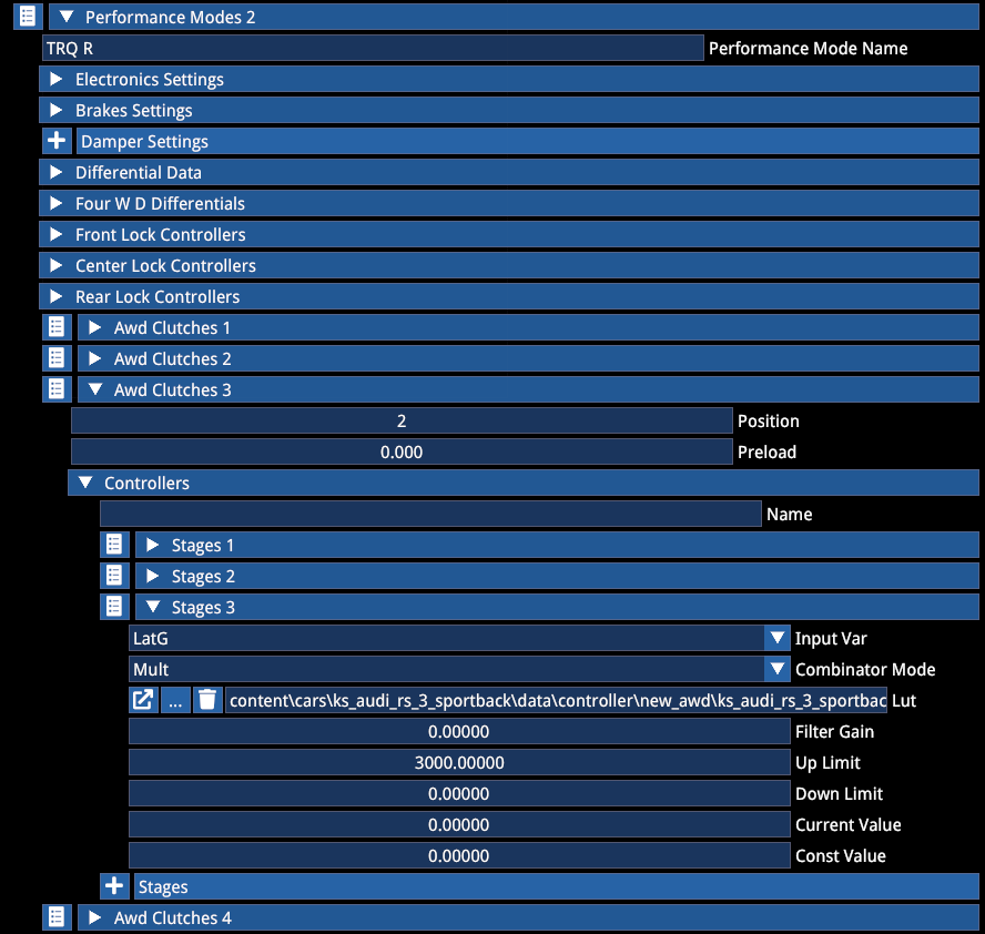
🔽 Performance Modes
Perf Modes allow you to combine a variety of functions and electronic settings into presets like Sport Mode or Comfort, or in the case of F1: Qualifying.
Also Mode dependent differential logics fall into this.
Performance Modes need to also be made available in the .carsetuplimits.
Dependency
Performance Mode settings should be dominant and override other definitions elsewhere and be initialized upon session start. However, if you experience issues, log a bug and until that is fixed, make sure to define the logic or settings in other files.
E.g. if the Performance Mode relies on a specific differential or clutch setup, define the same logic in the drivetrain as default.
Electronics
While several settings in the electronics are redundant and explained in their respective sections, some are unique to the Performance Mode:
| Parameter | Description |
|---|---|
| Ebb | Refers to the modes defined in the brakesystem |
| Engine Map | Refers to the Maps defined in the .carengine file |
| ERS Deployment map | Refers to the "Power Controllers" in the ERS section of the .car file |
| ERS Recharge Lv | Only exists in the Perf Mode settings. This is a scaling factor and refers to the Charge K value in the ERS section. 100 means 100% of the Charge K value |
| ERS Heat Charging | Equally refers to the Heat Charge K value in the ERS section, but this is simply an on/off toggle |
| Brake settings | Refers to different static torque and bb (not used anywhere by us) |
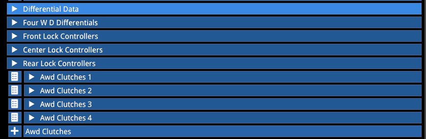
Differential & Clutches
Performance Modes exclusively allow changing the differential logic while in the car, particularly on cars with optional AWD, shifting torque to the desired axle or individual wheel based on a variety of physics parameters.
Differential Adjustments
| Option | Description |
|---|---|
| Differential Data | For FWD and RWD powertrains: changes mechanical differential properties |
| FourWD Differentials | For permanent 4WD powertrains: changes mechanical differential properties of any type (think Audi Quattro) |
| Front/Rear/Center Lock Controllers | Controllers allow precise electronic control of the locking torque of mechanical FWD/RWD/AWD differentials. Overrides the static mechanical definition. (Think Ferrari 296, M Active Differential, i30N as an FWD example). The output of these controllers is the locking torque of the differential |
| AWD Clutches | Allow driving torque to individual tyres by means of increasing clutch preload (think Audi RS 3 that is FWD + clutches for the rears, or BMW M8 that is RWD + clutches for the front) |
For each corner of the car, add a new clutch:
| Position | Corner |
|---|---|
| 0 | LF (Left Front) |
| 1 | RF (Right Front) |
| 2 | LR (Left Rear) |
| 3 | RR (Right Rear) |
- Preload: Defines a minimum locking torque
- Names are stored by pressing ENTER
- Each controller can consist of many stages, each with a different input variable
- The output of an AWD Clutch controller is the maximum amount of torque that can be transmitted through the AWD coupling clutch between driveline sections
When switching Performance Modes, all logics that should be changed need to be defined. If one logic is active in Perf Mode 1 and there is no new definition in Perf Mode 2, the logic of Perf 1 will remain active.
In theory, you can cheat by changing the differential from an LSD to a Torsen or anything else on the fly to achieve the desired effect.
⚠️ There are additional functions in the
.drivetrainfile allowing for individual left and right driven wheel diff lock control of 2WD cars.
4. COILOVER
⚠️ Some values in the coilover are ultimately superseded by the value in the
.carsetup!
Superseded values:
- Spring Rate
- Bump stop Range (distance from resting position to bump stop)
- Bump stop Force (spring rate of the bumpstop)
- Collar Position (resting position of the suspension)
- All Damper fast/slow bump/rebound values
- Helper spring K & Range (also known as auxiliary spring)
Yet, they are useful to have adequate simulation within the coilover file.
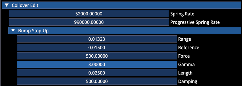
The hard definitions made here then are:
Progressive Spring Rate
For springs that aren't linear (needs ~10x higher value than spring rate to be noticeable!)
Bump Stop
Bump stop up = compression direction
| Parameter | Description | Example |
|---|---|---|
| Length | Size of the bump stop in meters | 2.5cm = 0.025m |
| Reference | Compression from which rubber stiffness becomes progressive | — |
| Gamma | Exponent of exponential stiffness increase | — |
| Damping | Inherent damping of the bump stop | — |
Damper Transition Speed Threshold
Damper speed (m/s) from which the fast damping rate applies.
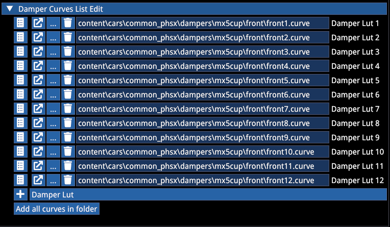
Damper LUT
- LUT List: Link to a
.DamperCurvesfile that contains predefined damper curves (usually racing dampers with multiple knees)
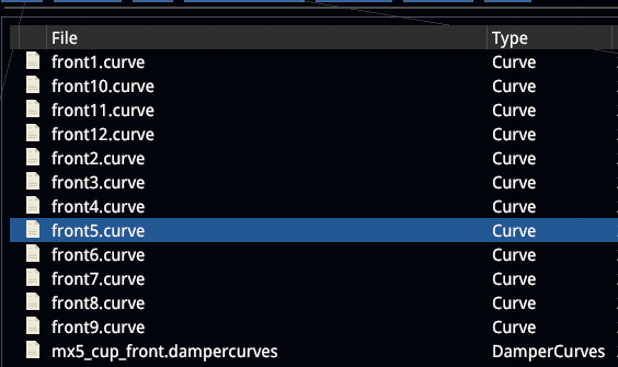
- Damper LUT Scale: Allows to use the same LUT for various cars by scaling them up or down
⚠️ Damper LUTs defined here require the
.carsetuplimitsto define the allowed click range (e.g. if you have 50 individual curves in a.damperCurvesfile, the adjustable damper range needs to be 1–50!)
Damper curve example:
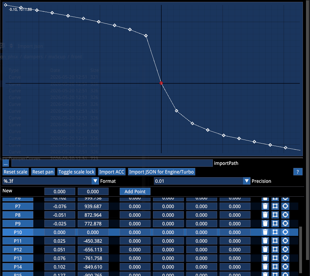
# Negative speeds = rebound movements, requiring positive force from the damper
# Positive speeds = bump movements, requiring negative force from the damper
Building these by hand would be unfeasible. A route for importing data is provided further down.
🔽 Sim
Plot rate: Shows forces on spring and bump stops depending on travel. The red line marks the start of the compression bump stop, green the start of the rebound stop.
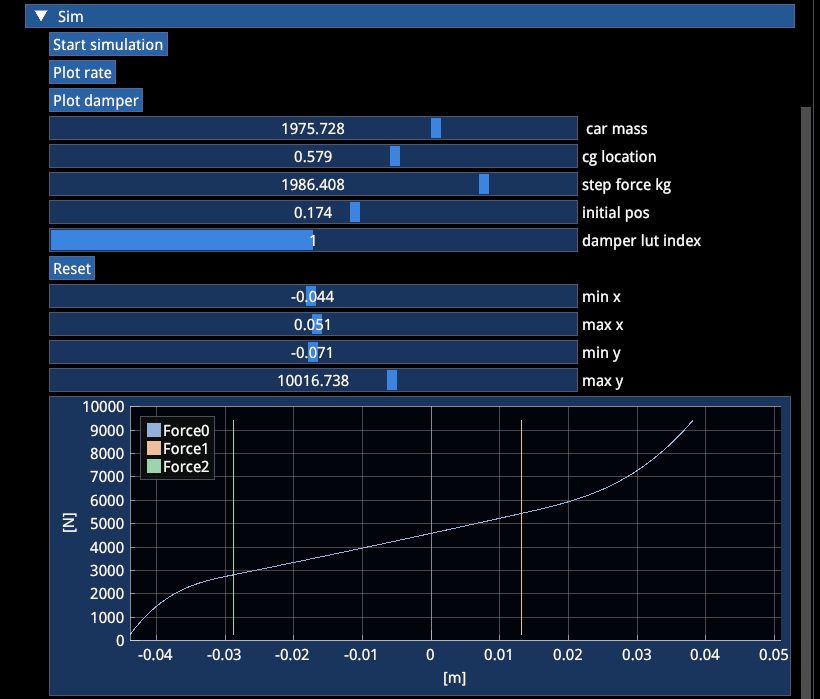
Damper plot: Shows force over damper speed, depending on slow/fast slopes and defined knee speed.
5. SUSPENSION
Here you can define various suspension type geometries.
🔽 Basic Data
| Parameter | Description |
|---|---|
| Hub Mass | Weight of the hub in kg (this is part of the total mass of the car and has influence on weight distribution. Heavily off weight balance often indicates a typo here) |
| Toe out | Leave 0 if you do not have data |
| Static camber | Leave 0 if you do not have data |
| Rim offset | Should be 0, only for fine-tweaking scrub radius without having to redo the entire geometry |
⚠️ ONLY FILL ONE TYPE ⚠️
Generally suspensions need millimeter precision, especially for correct camber gain and bump steer behavior. It is not advised to fiddle with the suspension in the editor until you find something that works. Ideally use engineering software to design your suspension and then copy over to the editor. All measurements originate from the center of the rim/tyre.
Types without coilover angle (utilizing Wheel Rate):
- DW Data
- Axle
- Multi Link
- Trailing Arm
Types with coilover angle (utilizing Spring Rate):
- Strut: Standard strut suspension including angle
- Strut Ml: Allows for more complex strut suspensions
- Multi Link New Data: Multilink with coilover angle
- DW Coil Data: DW with coilover angle
6. DRIVETRAIN
Traction Type
Defines the general layout.
| Type | Description |
|---|---|
| RWD | Standard Rear Wheel Drive |
| FWD | Standard Front Wheel Drive |
| FourWD | All wheels driven with 3 differentials + electronic logic if desired (Peugeot 205 T16, Audi Quattro, etc.) |
| AWD | RWD with option to direct torque to front wheels with "AWD Clutches" in positions 0 and 1 (M8 Competition) |
| AWDF | FWD with option to direct torque to the rear wheels with "AWD Clutches" in positions 2 and 3 (RS 3) |
Differential Data
| Parameter | Description |
|---|---|
| Power / Coast | Decimal % locking as a multiplier of input torque (future changes to come). 1.0 = 100% |
| Preload | Nm |
| Front share | For FourWD, decimal |
| TBR | Used with Torsen diff (5.0 = 5:1) |
Ignore all wear and temp, not active currently
Other Options
Drive train wobbling:
| Option | Description |
|---|---|
| ☑ Max Between Lsd and Elsd | Allows for a dynamic switch of logic while driving between mechanical LSD definitions and Front/Rear Lock Controller logic. Both are computed at the same time, while the bigger torque value will be applied |
| ☑ Has cockpit controls | Allows in-car differential adjustment according to the allowed range in .carsetuplimits (e.g. GT3 RS) |
The controllers work analog to the Performance Mode descriptions above.
Left and right lock Controllers allow for differential-driven torque vectoring logic. However, many torque vectoring or electronic diffs use targeted brake application instead. This can be built in the .brakesystem's "brake steer" section.
7. GEARBOX
General
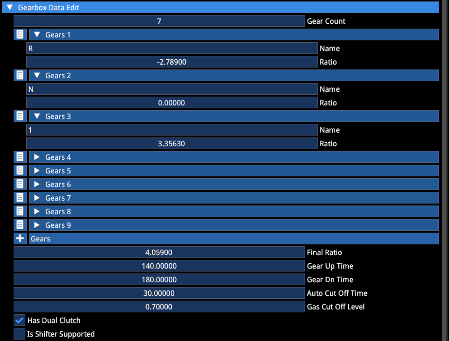
| Parameter | Description |
|---|---|
| Gear Up/Dn Time | In ms, defines how long the gear shift takes |
| Auto Cut Off Time | Defines the length of throttle cut |
| Gas Cut Off Level | Defines the amount of throttle during the shift. Advised to not turn this to 0 for manual gearboxes, else it acts as a flat shift assist players cannot turn off |
The default gearbox is a Sequential.
| Option | Description |
|---|---|
| ☑ Has Dual Clutch | Enables the DCT logic with near seamless gear changes |
| ☑ Is Shifter Supported | Enables H-Shifter gearbox |
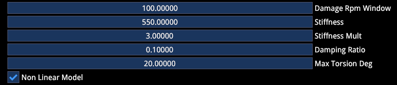
H-shifter Damage
Damage RPM Window: Defines the amount of damage accumulated based on the amount of time the grinding occurs on manual cars. Works in conjunction with:
validShiftRPMWindow (in .gearbox file): Defines the maximum allowed RPM difference between engine and drivetrain for a gear shift to be considered successful.
If the RPM mismatch exceeds this threshold, the shift fails and a gear grinding event occurs.
The valid window decreases by the Damage RPM Window value with each second of grinding.
Example:
Valid Window = 1000
Damage Window = 100
Grinding gears for 2 seconds reduces the Valid Window to 800. A total of 10 seconds of grinding will result in gearbox failure.
Controls Window Gain: Controls how much throttle input influences RPM synchronization during gear shifts.
The system blends between:
- Clutch-only RPM influence (controls window gain = 0)
- Clutch + throttle RPM influence
When throttle is released during shifting, higher values significantly reduce RPM mismatch. I.e. high values reward clean release of throttle during shifts, making miss-shifts less likely.
Downshift Protection
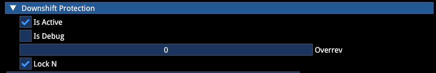
For Sequentials and DCTs:
| Option | Description |
|---|---|
| ☑ Is Active | Helps prevent overrevving |
| Overrev | Defines the allowed RPM above limiter (found in .engine) during downshifts |
| ☑ Lock N | Forces cars to become stationary before being able to shift to Neutral. Currently used to circumvent a bug that turns off the engine when DCTs shift to Neutral while driving |
Autoblip
The curve defines the throttle blip over time:
X = time (ms)
Y = throttle, decimal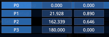
| Option | Description |
|---|---|
| ☑ Is Electronic | Forces the Autoblip to be on regardless of assist settings. Should be used on Sequentials and DCT. Also works when manual gearboxes use paddles (e.g. M2). Soon to be made functional for H-shifter inputs. |
Auto Shifter
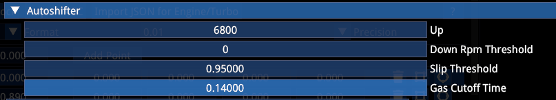
| Parameter | Description |
|---|---|
| Up | Target RPM for upshift |
| Slip Threshold | Helps prevent getting stuck in an up/downshift loop when tyres are slipping |
| Gas Cutoff Time | Same as above |
Ignore any Gear fatigue, not active
8. CLUTCH
Autoclutch
Needed for manual gearboxes when the player does not have a clutch and uses the autoclutch assist.
X = time (s)
Y = clutch engagement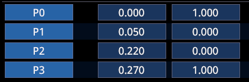
| Parameter | Description |
|---|---|
| ☑ Forced On | For DCT to have clutch during getaway even when clutch assist is off |
| Min Rpm | RPM before clutch starts engaging |
| Max Rpm | RPM where clutch is fully engaged |
| ☑ Use on Changes | Forces clutch during shifting even without clutch assist |
The standard clutch curve is S-shaped from 0–100. You can add any shape you want, e.g. with deadzones.
User input 0 = pedal pressed, clutch disengaged (0)
User input 100 = pedal released, clutch engaged (100)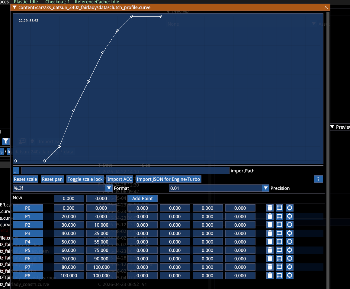
9. ENGINE
Power and torque values are @ the wheel.
Press "Simulation" at the bottom of the .engine file to open the torque plot.
General
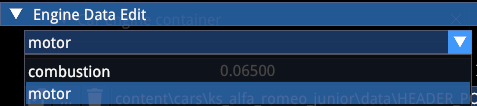
Type:
| Type | Description |
|---|---|
| Combustion | ICE (Internal Combustion Engine) |
| Motor | EV (Electric Vehicle) |
For Hybrids choose Combustion and add ERS in .cardata.
Power Curve:
X = RPM
Y = Torque Nm (turbo chargers act as a multiplier on top)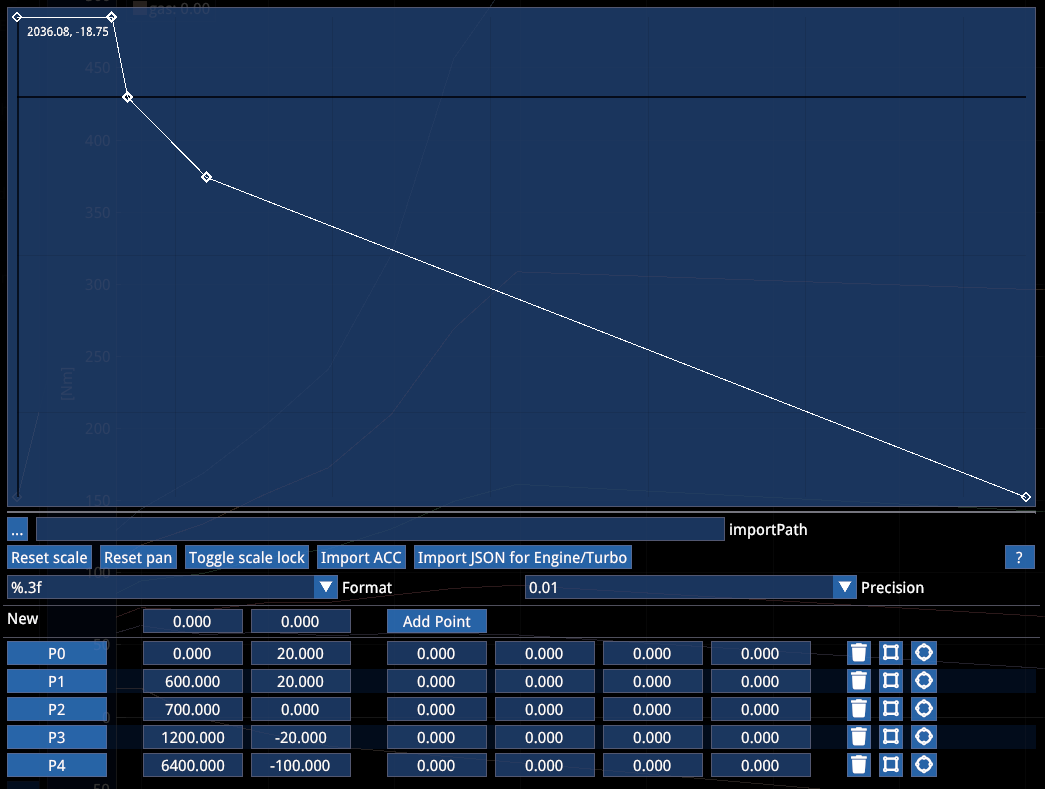
Coast Curve: Same as Power curve, but torque value should be negative.
E.g.: 0 torque will be your idle RPM, 20 is essentially the starter torque and the resistance of the engine to stalling.
Engine Maps:
Can be used to change power-related behavior while in-car.
| Type | Description |
|---|---|
| Type Cervone | In this model, torque modulation is governed by a law that depends on the throttle input and the square of the rotational speed (RPM). The behavior can be easily tuned using the Throttling Factor |
| Throttling factor | Controls the blend between the standard linear interpolation (lerp) of minimum and maximum torque and the RPM-loss-based model. A higher value increases the influence of RPM-dependent losses, while a lower value favors the standard torque interpolation |
| Type Gamma | This model is defined by three parameters: Throttle, Throttle Gain (k), and Throttle RPM Move |
Additional parameters:
| Parameter | Description |
|---|---|
| Throttle Lag up/dn | Allows to delay the effect of the pedal input |
| Minimum | Stalling RPM |
| Limiter | Max RPM |
| Limiter Cycles | Frequency of limiter, but works in conjunction with engine inertia, coast and power torque |
| Throttle Rev Choking | Currently in development. Attempt to better manage RPM limiters |
Start ECU Assist / Launch Control
Two logics are available. New logic is triggered with the ☑ use clutch checkbox.
The new logic has 2 phases. During the first phase a limiter controls RPM, while the clutch will try to match the desired tyre slip.
New method (☑ use clutch):
| Parameter | Description |
|---|---|
| Speed Range KHM | Speed range until launch control ends |
| Rpm Limiter | Holding RPM before launch |
| Limiter Cycles | Frequency at which limiter engages with RPM Limiter |
| Slip Ratio Target | Defines the targeted slip ratio |
Old Method (new is better, so no need to use this):
| Parameter | Description |
|---|---|
| Rpm Range | Defines smoothness of clutch |
| Clutch and Gas Gain | Regulate intervention |
Turbos
There are various methods to control turbo chargers (also Superchargers are turbo chargers, but without lag).
Turbos to load: Add turbos here. You can add as many as you want, their respective boost will be combined. You can either use multiple turbos with unique characteristics or you can use a single turbo and define a turbo controller to create whatever boost characteristics you desire. If you have two turbos, create two controllers. Else one might fall through unregulated and will produce the full boost defined in the .turbo file.
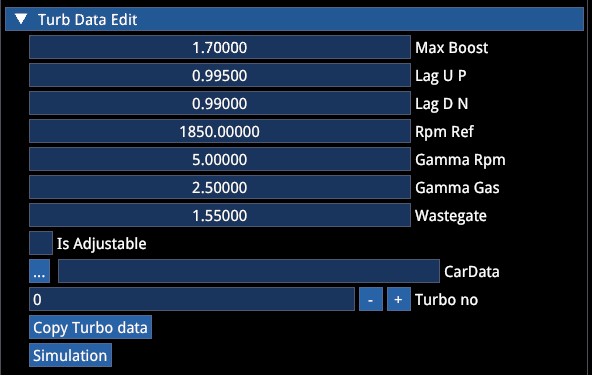
| Parameter | Description |
|---|---|
| Max boost | Peak boost output of the turbo |
| Lag Up | Defines delay when building boost |
| Lag Dn | Defines delay of pressure loss (think anti-lag) |
| ☑ is Adjustable | Enables in-car adjustment via MFD/hotkey — also requires .carsetuplimit definition |
Lag logic:
value = old_value + (new_value - old_value) * saturate(1 - filter)| Value | Lag in milliseconds |
|---|---|
| 0.999 | 3000ms |
| 0.990 | 300ms |
| 0.90 | 30ms |
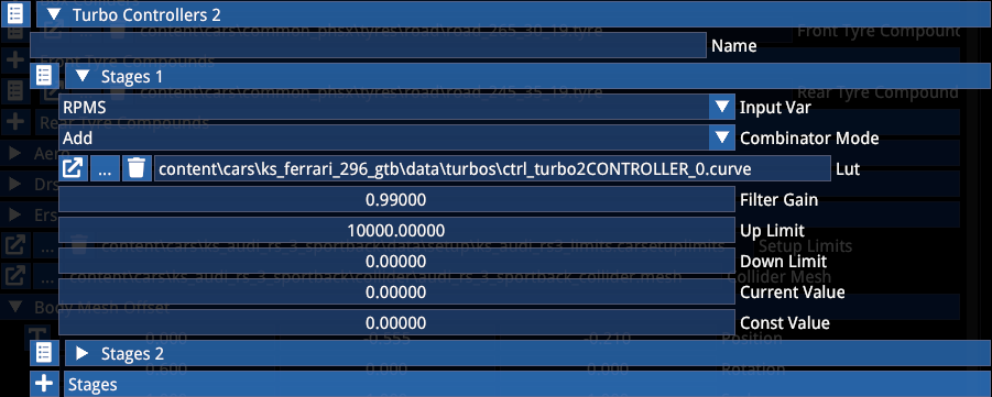
Turbo Controllers
They allow you to control the turbo pressure based on various metrics — within the limits defined in the .turbo file.
In the example below, the first stage is based on RPM and will tie the turbo pressure to that.
(Controllers have a separate section further down)
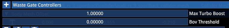
Max Turbo Boost and Bov Threshold have no physical impact, but are used as references for gameplay and audio to have a bit more freedom.
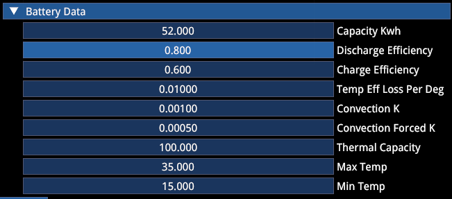
Battery Data
This section is for pure EVs. The coast torque curve influences the recharge speed.
10. BRAKESYSTEM
| Parameter | Description |
|---|---|
| Total Torque | Total brake system capacity. The torque will be split between front and rear axle according to the current brake bias |
| Front Bias | Overwritten by carsetup and/or onboard adjustment (☑ has cockpit bias enables the latter) |
| Bias Step | Overwritten by .carsetuplimits but currently also by the MFD's own step logic (bug) |
| Compounds | Brake pads (.brakes file). If no compound is defined, the hard-coded standard pads are used. Since this heavily interacts with the tyre temperatures, this is currently a WIP area |
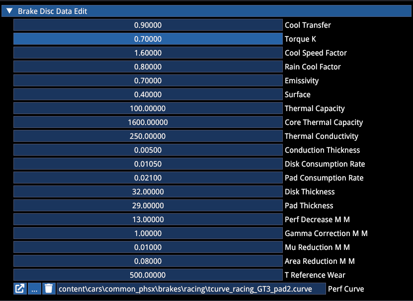
.Brakes File
Current suggestion is to not invest too much time here, as tyre temperature calibration is yet to happen.
The Performance Curve is defined with temperature in °C and a torque multiplier (1.0 = 100%).
Brake Controllers
Various options exist to control the brake engagement, particularly interesting for modern sports cars.
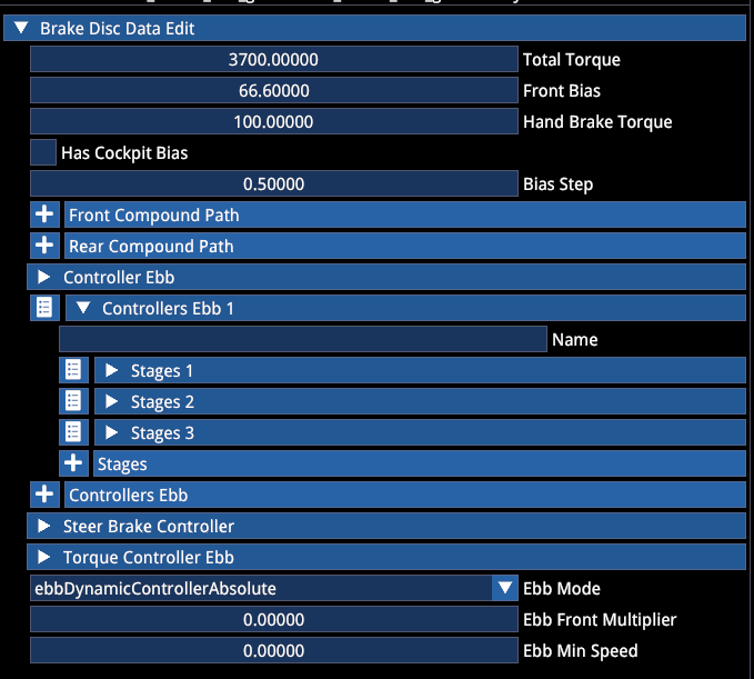
Electronic Brake Bias
Allows to create logics that shift brake bias forward and backward based on a variety of physics parameters.
EBB Mode:
| Mode | Description |
|---|---|
| Absolute | Sets the brake bias to the respective value (0.67 for 67%) |
| Relative | Shifts the brake bias by the respective amount from the original BB (e.g. 0.67 + 0.05 → 72% BB) |
Steer Brake Controller
Allows to create Automatic Brake Differentials, where the brake acts on the inside driven wheel to replace or assist the diff, or act as torque vectoring.
The output of the controller is Torque in Nm
⚠️ Important: To know which side the brake torque should be applied on, a stage as Multiplier is necessary, where positive values engage one side and negative the other.
E.g. X (input) = Lat G, Y = multiplier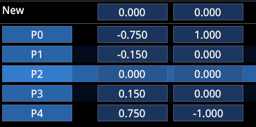
Our ABDs typically have 5–6 stages in order to cover all driving scenarios, combining G-forces, Speed, Slip, Throttle, over- and understeer. A rough ballpark torque to apply is in the 300–500 Nm range.
Torque Controller EBB
Allows for dynamic brake strength adjustment.
11. CONTROLLERS
Controllers are our multi-purpose tool for everything. Used correctly, they are very powerful and allow you to make complex definitions for behavior of car parts. Modern cars in particular have complex electronic systems integrating a lot of sensor data into decision making. Controllers allow us to mimic these systems to a reasonable degree.
As an example, we'll use a simple version of the Alpine's Automatic Brake Differential.
- The controller is part of the
.brakesystemin the "🔽 Steer Brake Controller" section - It utilizes only 2 stages and looks into slip ratio and lateral G forces to apply braking torque to the inside wheel
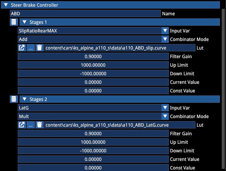
Each stage consists of multiple options:
| Option | Description |
|---|---|
| Input Var | Defines the variable the controller looks at for decision making |
| Combinator Mode | Allows you to switch between adding or multiplying the output value (in terms of a steer brake controller, the output value is torque to one or the other wheel) |
| LUT | A lookup table pairing the value of the input variable to the output value of the controller |
| Filter Gain | Defines a system delay |
| Up limit / Down limit | Defines a clamp to not exceed these values in this stage regardless of the logic |
| Current / Constant value | Rarely used. Current being a pass-through and constant being a clamp without any range (requires InputVar → const) |
Combinator example:
(example 4 stages: add, mult, add, mult) → (val1 * val2 + val3) * val4Filter Gain Values
| Value | Lag in milliseconds |
|---|---|
| 0.999 | 3000ms |
| 0.990 | 300ms |
| 0.90 | 30ms |
Example Analysis
In our example:
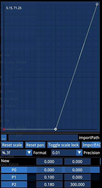
The first stage looks for the maximum slip ratio value between both rear wheels. Until a slip ratio of 0.1 no brake force is applied. From 0.1 to 0.18 the brake engagement increases, the response time is 30ms.
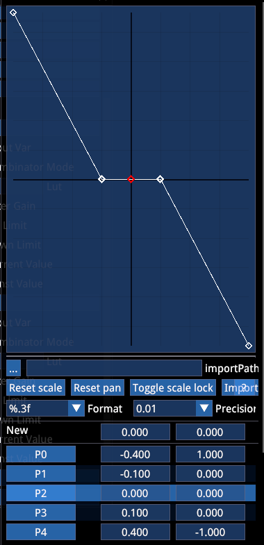
The second stage looks for Lateral G and multiplies the previously defined brake torque.
Until 0.1g in both directions no brake torque is applied (driving straight, essentially). Then, until 0.4g the maximum torque is engaged if the slip ratio conditions are met.
"+" and "-" define the side of the car where the brake should be applied. Since the max multiplier is 1 and the max torque from the first stage is 300, the maximum brake torque is also 300 Nm.
Input Variables
| Input Variable | Unit | Note |
|---|---|---|
UndefinedInput | — | — |
Brake | 0 – 1.0 | Brake |
Gas | 0 – 1.0 | Gas |
LatG | G | Left = -G, right = G |
LongG | G | Decel = -G, accel = G |
Steer | 0 – 1.0 | 1.0 equals the car's max steering input |
Speed | kph | Speed |
Gear | # | Gear |
SlipRatioFrontAVG | typically 0 – ~0.2 | Takes the average between the front tyres' individual current slip ratios (longitudinal) |
SlipRatioRearAVG | " | " |
SlipRatioFrontMAX | " | Takes the higher SR value between the two front tyres |
SlipRatioRearMAX | " | " |
SlipAngleFrontAVG | typically 0–10° | Takes the average between the front tyres' individual current slip angles (lateral) |
SlipAngleRearAVG | " | " |
SlipAngleFrontMAX | " | Takes the higher SA value between the two front tyres |
SlipAngleRearMAX | " | " |
OversteerFactor | ° | SlipAngleRearAVG - SlipAngleFrontAVG. E.g. 4 means rear wheel average slip angle is 4° higher than front average slip angle (oversteer). Negative values represent understeer |
RearSpeedRatio | Ratio | Ratio between the average rear wheel angular velocity and the average front wheel angular velocity |
SteerDEG | ° | Steering wheel angle in degrees |
Const | output value | Works in conjunction with "Const Value" field. The field will be ignored when Input Var is not Const |
RPMS | 0–20000 | RPM |
WheelSteerDeg | ° | Tyre steer angle in degrees |
LoadSpreadLF | Ratio | Ratio between left front tyre load and total front axle load |
LoadSpreadRF | Ratio | Ratio between right front tyre load and total front axle load |
AvgTravelRear | mm | Average rear suspension travel |
SusTravelLR | mm | Left rear suspension travel |
SusTravelRR | mm | " |
SteerYawDeltaLeft | — | steer + 4 * CarAngularVelocity. Compares the steer input with car angular velocity. Used for left tyre torque vectoring |
SteerYawDeltaRight | — | -(steer + 4 * CarAngularVelocity). Compares the steer input with car angular velocity (negative). Used for right tyre torque vectoring |
ErsChargeLevel | 0–100 (or 0–1) | Checks charge state of battery, e.g. to manage ERS output on modern F1 cars |
ErsCoastTorque | Nm | Checks coast torque of electric motors in hybrid cars, e.g. in order to manage brake bias shift (EBB) |
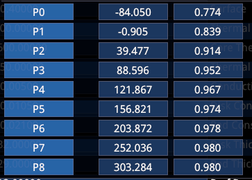
Look Up Tables
It's important to know the input variable and output needed in every use case. In many places the unit of input and output is not specifically mentioned — in other places it can be chosen.
E.g. as part of a controller you can choose from a variety of input variables, whereas the output variable depends on the system it's being used in.
| System | Input Var | Output Variable | Unit |
|---|---|---|---|
| EBB (electronic brake bias) | Controller: selectable | Brake Bias | Decimal front bias. E.g. 0.70 = 70% |
| AWD Clutches | Controller: selectable | Locking Torque per tyre | Nm |
| Turbos | Controller: selectable | Boost | Bar |
| KERS | Controller: selectable | Torque | Nm |
| Throttle | Pedal input % | Throttle % | % |
| Engine | RPM | Torque | Nm |
| Active Aero | Controller: selectable | Wing Angle | ° |
| Aero downforce | Ride height | CL/CD | Decimal |
12. TYRES
⚠️ PLEASE READ ⚠️
The tyre editor will allow you to tweak any value available in the model. However, you will not have control over the code and math connecting all parameters. We are continuously working on that and it will impact the tyres you create in unknown ways if you diverge from the current calibration. We strongly recommend to stay with the tyre as is to keep compatibility throughout updates. Ideally, you only select the "Tyre Compound" and initialize its dimensions.
Known issues in the model:
- Tyres require too much slip to produce grip (and therefore also response is slow)
- The Slip Ratio curve is too dynamic, especially in combined grip scenarios, leading to nervous throttle pickup
- Grip impact of tyre pressure and camber works too simplistically
These require code changes and cannot be addressed with tweaking values alone without moving the problem domain elsewhere.
Creating Tyres
To create a tyre, create a tyre file:
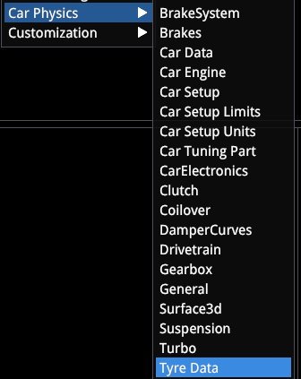
- Open the file
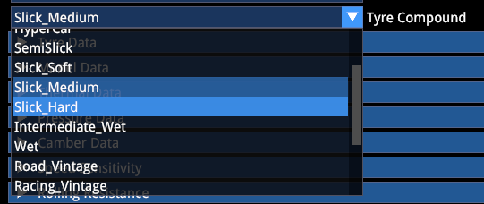
- Select the desired compound (all GT tyres are Slick Medium (!))
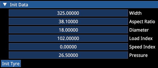
- Scroll to the "🔽 Init Data" section at the bottom
- Enter dimensions (speed index is not needed)
- Press "Init Tyre" → save the file
All model parameters will be set according to compound and dimensions.
If you use weird Init data, expect weird results.
13. CAR SETUP LIMITS
Car Setup Limits define what setup options are available, their range and steps per click of adjustment. If a value in the .carsetup is out of range, the game will enforce the .carsetuplimit values. This can lead to a dysfunctional car until .carsetup and .carsetuplimits are correct. This means even if the setup option isn't available to players, you still need to make sure the .carsetuplimits allow the value you chose for the .carsetup.
| Option | Description |
|---|---|
| ☑ Is Modifiable | Enables the setup option for the setup screen — if it has been implemented from UI side |
| ☑ Hide Value | Will convert the value to just the available amounts of steps, hiding the actual value |
| ☑ Is Negative | Allows to invert the UI slider and is used for the Caster currently (caster being a negative longitudinal offset of the top mount of the suspension in meters having a negative value and thus "more caster" would be to the left of the slider) |
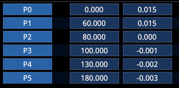
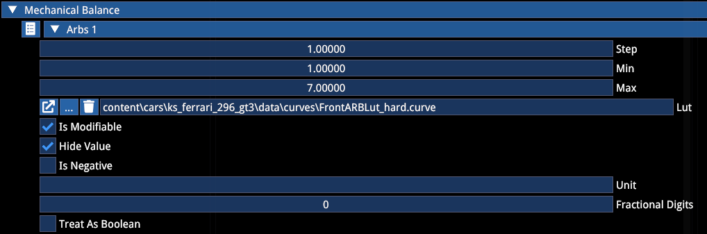
| LUT | If a LUT is defined, you can have non-linear steps which is typical for ARBs. The steps then need to be according to the LUT (usually 1 click) and the min and max are the 1st and last possible click |
LUT example:
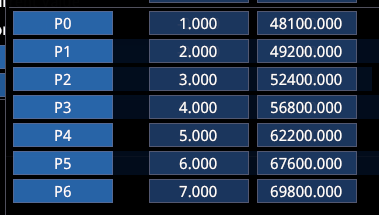
In this case, the Step must be "1", the min "1" and the max "7". If you want to only use a smaller part of the LUT, you could also define from min "3" to max "5", resulting in only 3 clicks. A step of "2" would result in only settings 1, 3, 5 and 7 being selectable.
| Parameter | Description |
|---|---|
| Unit | Unit override does not work currently |
| Fractional Digits | Does not work |
| Treat as Boolean | Not needed nor used anywhere |
14. CAR SETUP
The .carsetup file is the default setup of the car. There can be various for different mechanical presets and wet conditions (with wet tyres for race cars).
All values in the
.carsetupoverride values entered in other places, like cardata.
However, values in the default Performance Mode (1) override .carsetup values (e.g. GT3 RS dampers) — we consider this a bug and seek to address it.
The car setup needs to be linked in cardata.
Once you open a car setup the "Setup" widget will open:
Press "Start Auto Setup" to start the simulation and let the setup converge — the car will be elevated to the set ride height and suspension elements will fall into place. Here you can make adjustments to the setup as if you were in-game, while carsetuplimit ranges are respected and only adjustable settings are shown. After converging is done ("Wait while working on setup" disappears), make sure to save the setup. You will see the values for "collar position" change in the setup file — these are computed, do not adjust them manually.
NOTE: In the future we will move away from directly selecting ride height. Ride height will instead be a result of all other settings.
15. CALIBRATING SUSPENSION
Based on suspension geometry, the car's weight and dimensions, Base Y, ride height settings, etc. the default suspension position is computed. However, if the current .carsetuplimits do not allow the correct range for the suspension position to settle, the auto-setup will fail, as the suspension is not allowed to move further.
For this you will need:
.carsetup.carsetuplimits- Start the simulation
- Open Suspension debug
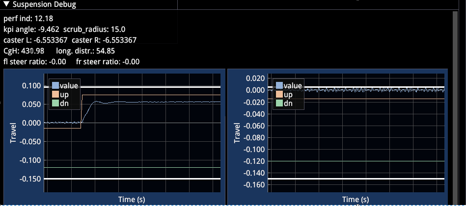
The suspension debug shows:
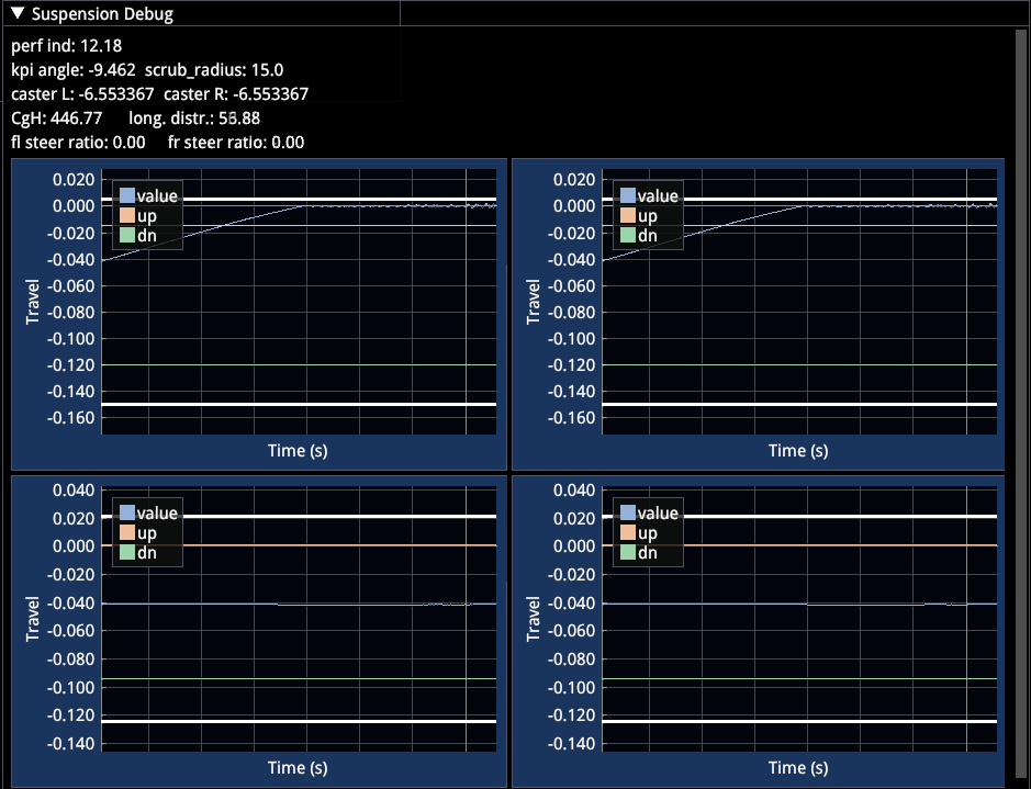
| Element | Description |
|---|---|
| Blue line | Suspension collar position for all 4 corners of the car |
| Red line | Compression bump stop start |
| Blue line | Rebound bump stop start |
| White lines | FINITE end of travel (this was not the case in AC1 and ACC, suspensions and bump stops got stiffer but never rigid) |
The screenshot shows the attempt of the auto-setup to lower the front suspension to the requested position, however, the allowed range is too small and the suspension reaches its end of travel.
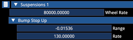
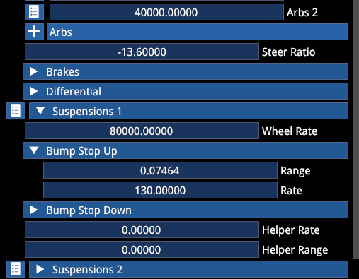
Calibration steps:
Open the .carsetup and go to 🔽 Suspension 1 (and copy to 2 afterwards), 🔽 Bump stop up and adjust the Range. In this case the missing range is quite large, so we're making a big adjustment by several centimeters and start the auto setup again.
Adjusted:
The front left now reaches a final position (of course the rebound range — Bump stop down — would need adjustment now, too), while the front right still fails, as we did not yet adjust it.
Every change to Base Y, the suspension geometry or the ride height will likely require you to re-align the suspension, meaning that this should be more like your last step in the entire process, as otherwise you will be doing loops.
16. DATA IMPORT
Since a lot of data in the game is based on .curve files — or look up tables — you might want to speed up the process. There are various options.
Aero Map Import
- Open a
.surface3dfile - Scroll to the bottom
- Click "..." for the import path and navigate to the CSV (sample file tba)
- Calculate interpolation
- Save
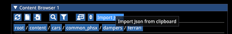
General JSON Import
In the content browser is an "Import Json" button. It will work when the content of a JSON with the correct structure is in the clipboard (i.e. Ctrl+A, Ctrl+C → "Import Json").
Structure:
// Header needs filename and path, the file will be created
// t = X
// value = Y
// The anchors aren't used but need to be there
// FILENAME=content\target_folder\desired_name.curve
{
"points": [
{
"t": -1.1,
"value": 2499.999756,
"anchor_left": {
"x": 0,
"y": 0
},
"anchor_right": {
"x": 0,
"y": 0
}
},
{
"t": -1,
"value": 2500,
"anchor_left": {
"x": 0,
"y": 0
},
"anchor_right": {
"x": 0,
"y": 0
}
}
]
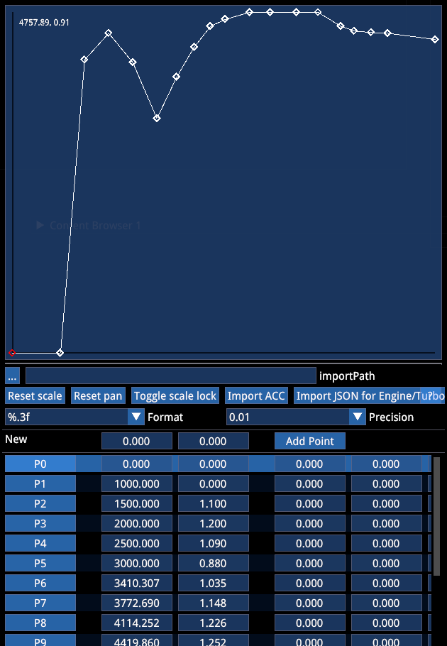
}Alternative JSON Import
A different JSON structure works when opening any existing .curve file.
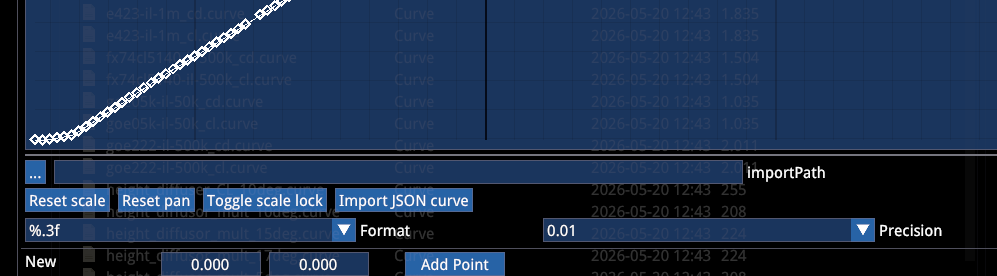
- Click "..." and navigate to the
.jsonfile - Click "Import JSON curve"
The structure is inexplicably different here and omits the anchors:
{
"values": [
{
"x": 0,
"y": 1
},
{
"x": 91,
"y": 1
},
{
"x": 392,
"y": 1
}
]
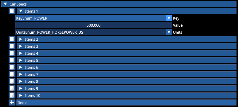
}17. UI CAR SPECS
You can add both numeric specs and detailed description to your car, as well as a detailed setup guide.
Numeric Specs
You can add car specs to the main menu car selection.
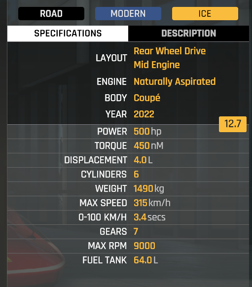
The technical specs are at the bottom of the mechanical presets:
Description Texts
The UI, Setup and customization texts can be added in the mod's uiresources folder in .loc files:
| File | Description |
|---|---|
en.loc | Description text for the UI |
en.cars.loc | Include matching cleartext for customization keys |
setup_en.loc | Setup notes |
References
- Kunos Simulazioni, AC EVO Car Modding Pipeline - Physics Official Documentation