
4. Functional Mesh Elements
ANALOG INSTRUMENTS
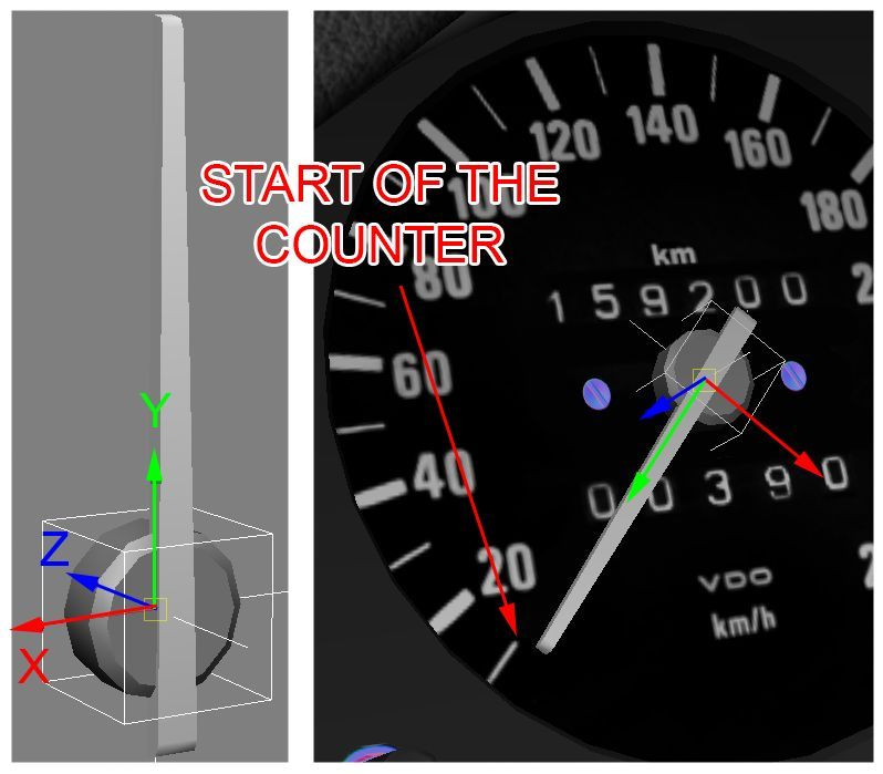
To animate a needle on the dashboard, the ARROW_ mesh needs to be placed under a proper null. Just as other objects, ARROW_ nulls must follow specific conventions: ARROW_SPEED ARROW_RPM ARROW_TURBO ARROW_FUEL ARROW_WATER_TEMP ARROW_TIME *ARROW_LIMITER Each ARROW_ null must be linked to the COCKPIT_HR null! Each instrument is controlled by specific values in the analog_instruments.ini script, located inside “content/cars/car_name/data” folder. The needle mesh must be created in neutral position and linked as child of a specific null. The arrow then must be rotated to the 0 position as shown in the image above. The Y axis determines the arrow position on the gauge and must be placed at 0 (ZERO) or the start of the gauge at hand. Note: Z axis must always point FORWARD *The ARROW_LIMITER is a tell-tale found for example in the Lotus 49 and Lotus 72D cars, showing the maximum RPM in a given stint. The rotation of the ARROW_LIMITER null must be the same as the ARROW_RPM null, and it requires NO script, as it is controlled from within the core engine. You can use the Data Scripts tab in the KS editor to set up the analogue scripts (see EDITOR section). To ensure compatibility in the future, if present, set up gauges that are currently not supported by the engine in a similar fashion, with name conventions that are consistent with the existing rules and the function of the instrument: ARROW_VOLTAGE ARROW_OIL_TEMP ARROW_OIL_PRES ARROW_FUEL_PRES ARROW_WATER_PRES LEDs and DIGITAL DISPLAYS It is possible to have various LEDs and indicator lights light up in the cockpit during driving. It is recommended to make the cockpit dynamic with as many functional items as possible.
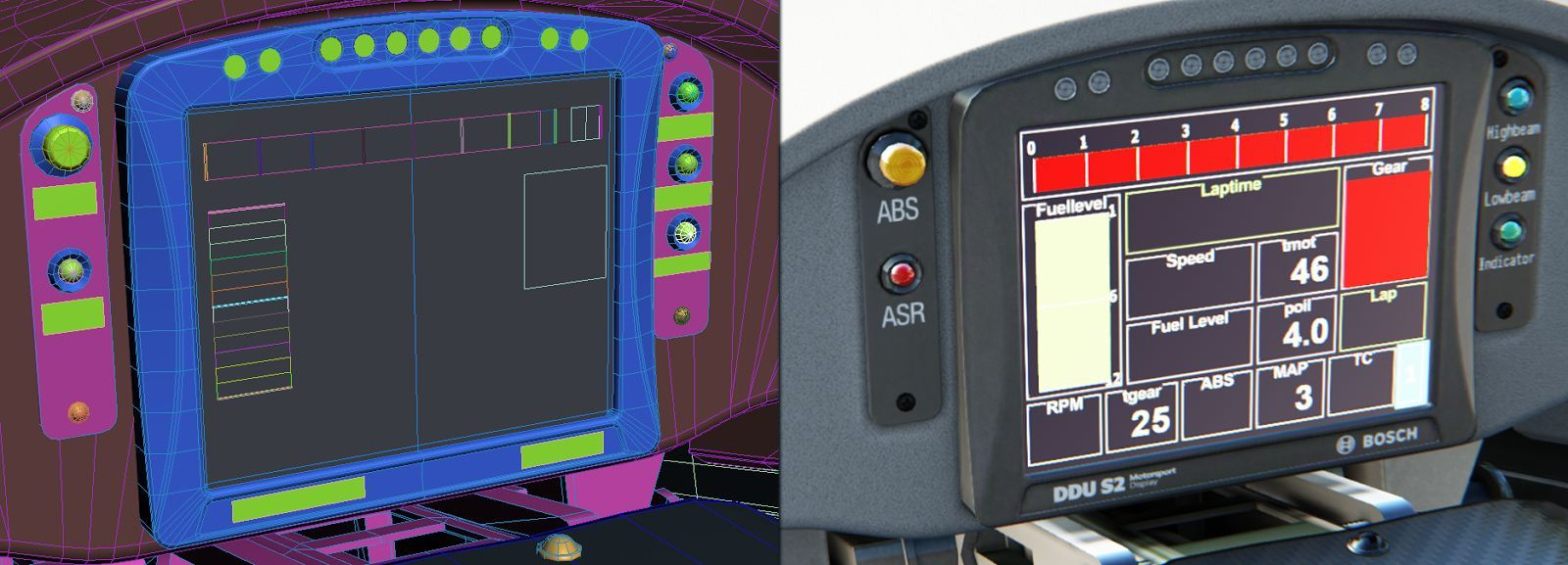
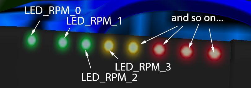
Each individual LED (such as for RPM, boost or KERS) or bar TAG must be a separate object and numbered in a series: LED_RPM_# where the “#” is the number of each specific item in a series TAG_RPM_# KERS_CHARGE_# KERS_INPUT_# TURBO_#
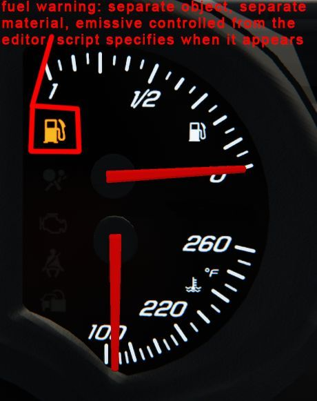
Some cars have multiple displays and it is possible that certain items (such as RPM) are shown in more than one screen. In this case, make sure that you differentiate between the two readouts: LED_RPM_1_# and LED_RPM_2_# etc. For functional LEDs or warning lights, each item must be a separate object, using the following naming conventions: LED_LIGHT headlight indicator light LED_FUEL fuel warning light LED_KERS KERS status light LED_IGNITION ignition status light There are two ways to control specific items on the dashboard. The first one is where the mesh is always present and the script controls the emissive value on a per object basis. This is the method used for RPM LED series, headlight indicators and ignition status lights. With the second method the mesh is disabled by default and the script controls how and when it should appear with the shader and object properties set up in the editor. It should be noted that the meshes appear in the editor and the showroom. This is used for dynamic RPM bar graphs, boost bar graphs, fuel level bars, shift indicators, fuel warning lights and KERS bar graphs.
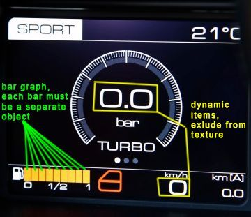
NOTE: If in the second case the item is a light with emissive values, it must also use an individual material with the desired emissive value set in the editor (e.g. fuel warning light). NOTE: It is very important that you do extensive research about dashboard functionality and digital screens (if present) and prepare the model for dynamic displays. When creating the texture for the digital display, you must take into consideration the dynamic readouts that are supported by the engine and must not include them in the static diffuse texture.
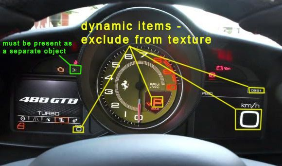
NOTE: Do NOT use the convention _01, _02, _03 etc. for single digits for the suffix of tag object names, always use _0, _1, _2 etc. E.g. LED_RPM_0, LED_RPM_1 etc. The following items are currently supported by the game engine: Time Gear Speed RPM Water temperature Fuel level (bar graph) Fuel level (litres) KERS charge (bar graph) KERS input (bar graph) Turbo boost (bar graph) Turbo boost (pressure) Lap time Previous lap time Difference from previous lap TC setting ABS setting Headlight indicator Fuel warning light Current lap Total laps Ambient temperature Km with current fuel left KERS charge readout Estimated fuel Any RPM-dependent status indicator Tyre pressure G-meter Placeholder script for any static text or numbers IMPORTANT: If there is a digital display, create a NULL called DISPLAY_DATA with the orientation shown in the image below. If there are more displays, use a serial number (DISPLAY_DATA_1 etc.) to specify each individual screen. The DISPLAY_DATA null is the reference for the items in the digital_instruments.ini, it serves as a reference point and makes sure the text appears on the same surface as the display. For this reason if the display is rotated/tilted, the null must follow the same orientation. To avoid clipping, place the null so that its pivot point is in front of the mesh by a few millimetres and not directly on it. NOTE that the above list is not complete. Please visit the following link to see a community and dev-assisted thread on the official support forum for a complete list of digital scripts and their implementation: http://www.assettocorsa.net/forum/index.php?threads/analog-digital-instruments-lights-q-a-request-official -support-here-check-first-post.12249/ DISPLAY_DATA null orientation and example for KERS bar graph:
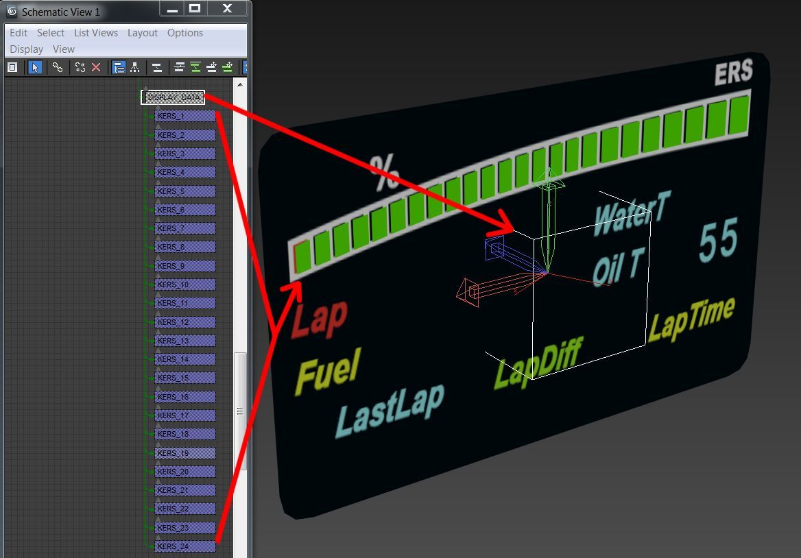
NOTE: When the display is located on the steering wheel, the DISPLAY_DATA null and all the TAG/RPM mesh objects must be a child of the STEER_HR null to make sure they rotate along with the steering wheel.
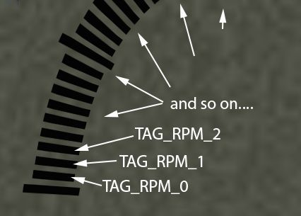
DIGITAL PANELS
Digital panels can be used for two functions: Push-to-Pass status and on-track Position. This feature requires a digital_panels.ini in the car’s data folder and pre-drawn numbers in the your_car/texture/display_panel folder. As an example, take a look at the content/cars/ks_audi_tt_cup/texture folder in your game install folder. You will also need a parent NULL (e.g. DISPLAY_PANEL), with the same orientation rules that exist for the digital instruments (see above). Position Use the following script to activate the function:
[FULLPOSITION_SERIES_0]
PREFIX=textName_ prefix of texture names located in car_folder/texture/display_panel
POSITION=
PARENT=DUMMY parent dummy name
START=0 postfix start
END=9 postfix end
DIGIT=1 set 1 for second digit, 10 for first digit
WIDTH=30
HEIGHT=40
COLOR=255,255,255,255
INTENSITY=2
Push-to-Pass Use the following script to activate the function:
[PUSH2PASS_SERIES_0]
PARENT=PANEL_P2P name of parent dummy
POSITION=0.0615,-0.068,0
WIDTH=0.124
HEIGHT=0.137
TRIGGER=0
PREFIX=num_ prefix of texture names
COLOR=255,255,255,255
INTENSITY=40.0
START=0 name postfix to start from
END=9 name postfix to end at
DIGIT=1 (=1 for second digit, =10 for first digit)
BLINK_HZ=5 blink rate when activated (=0 for no flashing)
P2P status led
[PUSH2PASS_LED_0]
OBJECT_NAME=LED_P2P
EMISSIVE=0,0,800
DIFFUSE=0.35
INVERTED=0 for inverse function
BLINK_HZ=0 if higher than 0, it blinks
Known limitation: in replays, the P2P and displayed position status is not communicated, which is why the panels will show incorrect or placeholder values.
SEATBELTS
The cockpit contains two different mesh objects for the belts: One for the belt ON and another for the belt OFF. These two meshes must be linked as a child of the null COCKPIT_HR and must be named as follows: CINTURE_ON for the belt on the driver when is driving CINTURE_OFF for the belt on the seat, without driver (showroom view) NOTE: The names are in ITALIAN (CINTURE = SEATBELT)…. To create the proper mesh of the belt on a driver, place the driver first, then animate it and verify how the arms move in order to avoid compenetration with the belt mesh.
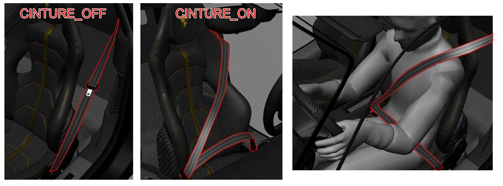
The seatbelt mesh must be modelled also in the cockpit LR but only the CINTURE_ON mesh. When you see the cockpit LR it means that you are in game, not in the showroom, so a driver is in the car and you have to show the CINTURE_ON configuration only, without the belt being separated from the rest of the cockpit mesh.
LIGHT MESH AND SCRIPTS
Each car must have individual objects. The light mesh objects must be separated and detached from the body of the car and use specific naming
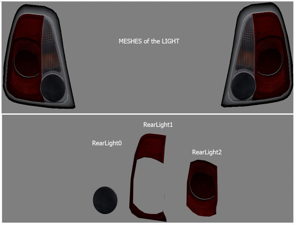
conventions. The mesh name must be controlled from the lights.ini script. The same scripts include the instructions for the ON/OFF conditions, as well as the light emission colour. Example image on the right: The mesh of the light is made from different parts, which are divided according to their function. Some examples: Position lights, brake, rear, standard front lights, high beams etc. Note: There is no need to split the lights up as “right” and “left”. They can be one mesh because they turn on together. IMPORTANT: similarly to the dashboard, please do an extensive research about light functionality, and strive to implement as many functions as possible. Each light source must be detached as a separate object, avoid keeping all the difference reflectors and bulbs in one object. This way, each element can be controlled individually to achieve realistic results. A good example is shown in the image below:
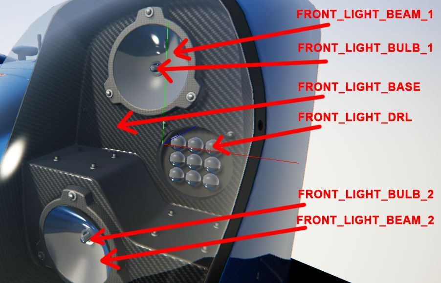
Open the lights.ini script located in the “data” folder The script contains the following values:
[HEADER]
VERSION=3 Script version. Keep this value like is.
[BRAKE_0]
NAME=REAR_LIGHT name of the mesh to light up
COLOR=500,60,40 RGB value when you press the brake pedal
OFF_COLOR=50,12,8 RGB value for position light when brakes are off
[LIGHT_0]
NAME=FRONT_LIGHT name of the mesh to light up
COLOR=240,195,180 RGB emissive value when the front light is on
OFF_COLOR=50,50,70 RGB emissie value for day-light (optional)
In the above example: The NAME= value affects a mesh called REAR_LIGHT (as seen in the image above). The COLOR= value assigns a colour when the brakes are on (you are pressing brake pedal). The line below OFF_COLOR= is the emissive value of the brake light (in some cars, the same mesh is lit up when you turn the lights on and when you brake). Different functions and colours can be assigned to different meshes. As an example, the value COLOR=3,0,0 assigns a specific colour to the light. The mesh is lit using HDR and there is no maximum limit of intensity. The values for the COLOR= parameter are in RGB 0 to 1 range, so a value of 1 means the maximum value of the RGB scale (256). The values can go over 1 if more intensity is needed. As an example, a value of 240 is given to the [LIGHT_0] section, in order to produce a strong glow. NOTE: for a glowing brake light we recommend an R (red) value between 150 and 850. For day running lights, we recommend values between 40 and 100, while for high beams, we recommend values ranging from 250 to 800. NOTE: the dashboard headlight indicator lights and the dashboard lighting are also controlled by the lights.ini. The dashboard objects and any other objects that light up in the interior must be detached and named according to the following convention: LIGHT_GAUGE_# LIGHT_INTERIOR_# Don’t forget to detach the objects and link them to their respective dummies if they are located on moving objects (e.g. the steering wheel) Modern Formula cars can use the following script for ERS status flash light at the rear:
[HEADER]
VERSION=3
FLASHING_BLINK_TIME=0.35 Blink length in seconds
FLASHING_REPEAT=1 Number of flashes on activation
KERS_BLINKING=1 Line means KERS blinking is enabled
NO_LIGHT_SWITCH=1 Line means it will not work as headlight
[LIGHT_0]
NAME=g_Rain_Lights
COLOR=180,0,0
PITLINE=1 1 means it flashes in pitlane
KERS=1 1 means it flashes when KERS harvest is active
SPECIAL=1 1 means light toggle is disabled
Use the following script to use flash function for headlights and flashing pitlane lights:
[HEADER]
VERSION=3
FLASHING_BLINK_TIME=0.15
FLASHING_REPEAT=8
[LIGHT_0]
NAME=LIGHT_FRONT
COLOR=530,420,50
FLASH=1 1 means will flash when flash toggle is pressed
[LIGHT_1]
NAME=LIGHT_RAIN
COLOR=95,0,0
PITLINE=1 1 means it will flash in pitlane
SPECIAL=1 1 means light toggle is disabled
SKINNED MESH
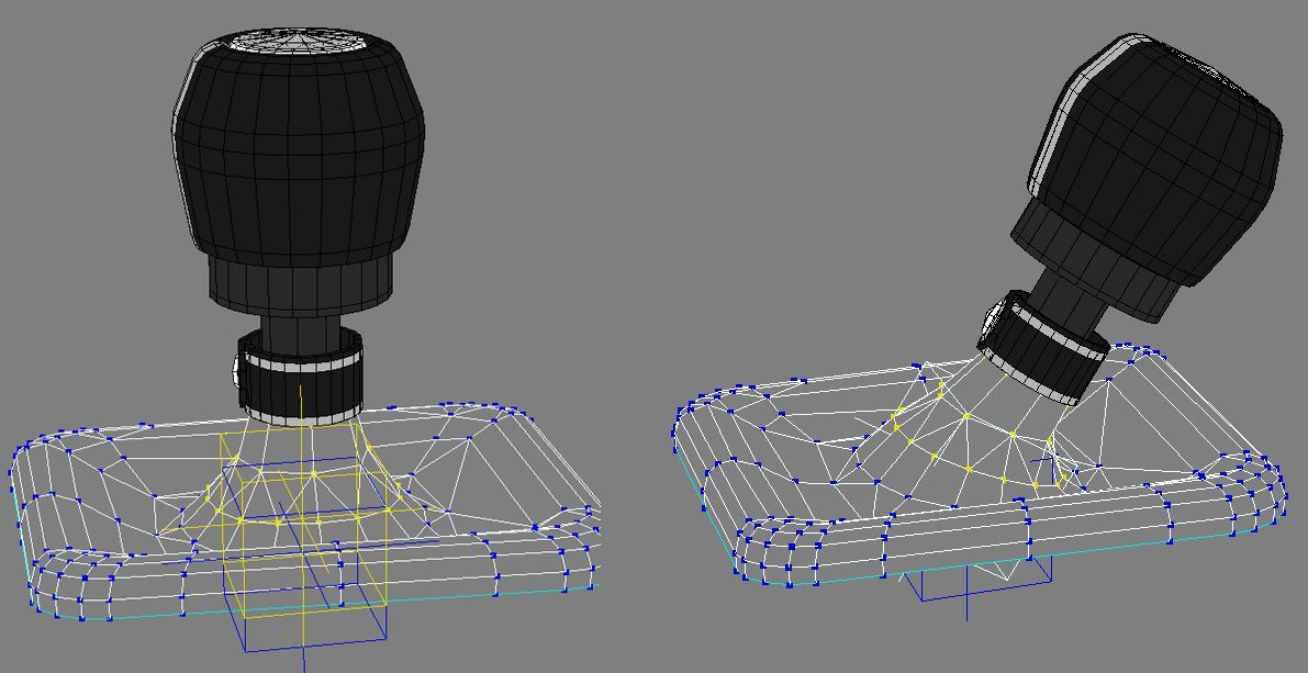
FBX skinned mesh objects are supported by the game engine. Skinned mesh objects can have as many bones as necessary but no more than 4 bones influencing a single vertex. A good example of skinned mesh is the driver (explained later) or the gearshift lever with a fabric skirt at the base of the lever. The example image up here show kind of usage that you can do. Rules for creating a skinned mesh:
- All vertices must be influenced by at least one bone. If a vertex is not influenced by a bone, its world coordinates will be 0,0,0, resulting in a long polygon that spawns from the center of the 3D world until your space position. A non-skinned object can be linked with a skinned mesh. Connect the non skinned object as a child of the skinned mesh. In the above image, the skin has 2 bones but the handle is a parent of the non-skinned yellow null.
- Every material with a skin rig must be unique. A material cannot be used on a standard mesh and at the same time on a skinned mesh. Two different materials must be created, one for the standard mesh and another one for the skinned mesh.
- The skinned-mesh dedicated material, must be KsSkinnedMesh or the KsSkinnedMesh_NMDetail. The animation works only when the skinned material is assigned to the skinned mesh.
- The skinned mesh must have the pivot in the 0.0.0 coordinates of the world. It can be child of another dummy, but this dummy must also have the coordinates of 0.0.0. We usually put the skinned mesh of the gearshift or something else in the cockpit as the child of the cockpit dummy/null. And the cockpit Dummy/null is usually in the 0.0.0 coordinates. Or you can simply leave the mesh free without linking it to any node. NOTE: Do not use this material on a standard mesh without bones. Avoid using skinned mesh on suspension parts! For springs and rubber parts use scale animation.
DRIVER POSITION AND MESH
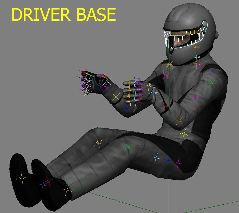
A copy of AC driver with the bones skinned, basic animation of the steer rotation, helmet and some textures, is provided as an example template. It can be placed inside any custom car. For a proper placement follow these steps: If you want to use a custom driver mesh go to the section CUSTOM DRIVER, otherwise follow these steps:
- Import the template file DRIVER_BASE.fbx in your 3D application. You should see the driver as in picture. Inside the template, a basic steering wheel rotation animation is provided as an example. The animation consists of 200 frames. The neutral position is on frame 100. From neutral (100) to 0, the steering wheel rotates to the left. From neutral (100) to 200, it rotates to the right.
- place your driver on the seat, with his hands on the steering wheel. Probably some modifications of our animation template will be necessary.
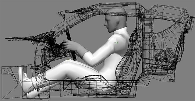
The image here shows an example placement: The driver mesh and position can now be exported and it will contain the correct hierarchy, and the correct names for the bones and various objects.
IMPORTANT:
Remember to set the unit in EXPORT (for the provided pilot) to Meters. If not, the editor will produce a weird position of the bones and a wrong result. Keep the same GENERIC UNITs in your 3D software. This is needed because of the original scale of our pilot is 1 and must remain 1 even when exported. For a bone created with a scale of 1 inside 3dsMAX or MAYA, this problem should be not present.
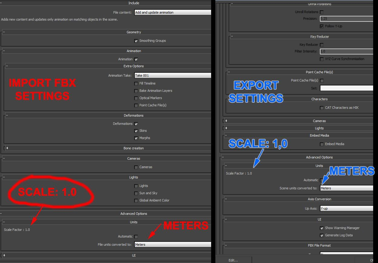
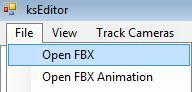
How to export the driver base position from the editor:
- Open in the editor the FBX file with the driver placed in the correct base position.
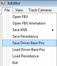
- Save Driver Base Pos A file named driver_base_pos.knh is created and stored in the same folder where the source FBX is located. This file must be placed in the following path: AssettoCorsa/content/cars/CAR-NAME/ where car-name is the car’s folder. The game engine will load the driver and place it using the correct position information stored in the driver_base_pos.knh file.
DRIVER ANIMATIONS
The provided template file DRIVER_BASE.fbx contains a basic example of a 360° steer rotation loop animation. This animation will probably not match the steering wheel of your car’s design. The animation must be modified to match your custom steering wheel dimensions and placement. Note: The animation must be 200 frames where frame 0, frame 100 and frame 200 match to allow a LOOP animation. For 3DS Max users we have prepared an animation rig that can be downloaded from the Driver animation folder in the Dropbox link. After editing the animation, save the keyframes of the arms NULLs only and export the FBX with ONLY the animated parts. Animating the pedals is not supported yet. The image below shows the hierarchy:
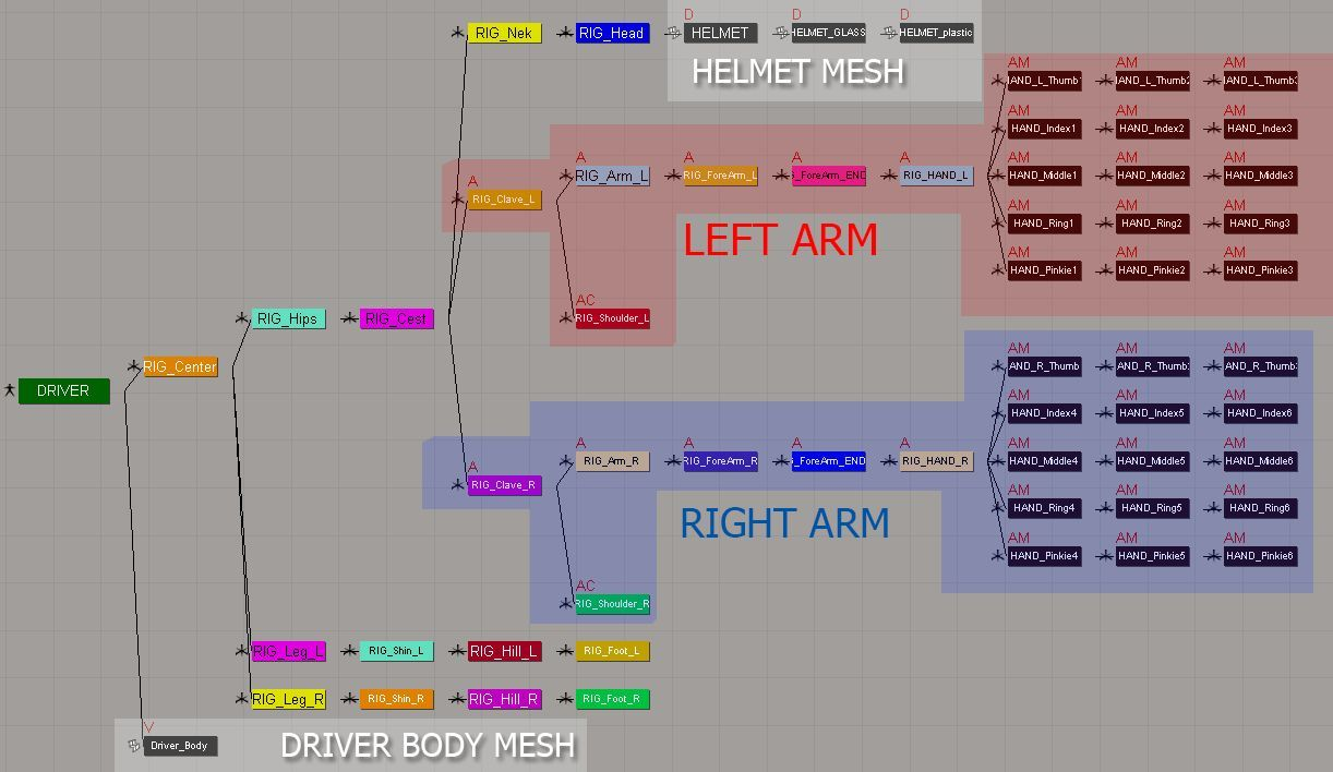
The bones of the arms are highlighted in the blue and red area in the image, and every bone is parent of the RIG_Clave_L and RIG_Clave_R bones. To animate the hand that does the shifting, animate the arm bones from RIG_Clave_L/R up to the fingers. To animate the paddle gear change, animate the fingers only. For every animation you must export a copy of the driver.fbx with ONLY the animated parts needed for the desired clip. Example: Export driver.fbx with the steering wheel animation only, then another one with gear animation only etc. Store the driver animations with the names indicated below in the animation folder of your car project folder with all the fbx files and textures. Steer.fbx for the 360° steer rotation Shift.fbx for the gearshift animation Shift_up.fbx for the paddle shift up Shift_dw.fbx for the paddle shift down See the section EXPORT ANIMATIONS FROM THE EDITOR for instructions on how to create a clip. Note: Always verify that the car shift animation and the driver shift animation have the same number of frames so that the animation is perfectly synchronized in the game. Warning: There is typo in the name of the “neck” bone, which is spelt as “nek” by error. Albeit being incorrect, the game still works with this wrong name, so please do NOT correct the typo and keep it “nek”.
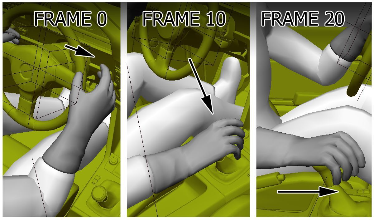
Example: When the driver changes gear, his arm starts the animation with the hand slightly distant from the steering wheel. (see image below) On frame 0 the hand is slightly away from the steering wheel. On frame 10 the hand is on the gear lever. On frame 20 the hand moves the gear lever. Be sure that the gear lever animation is synchronized with the hand. For example, if the hand needs 10 frames to reach the gear level, the gear lever must have 10 frames in the static position before it starts to move. NOTE: See the following forum thread for a driver rig and explanation to be used in 3DS Max (many thanks for the_meco): http://www.assettocorsa.net/forum/index.php?threads/custom-steering-animation-rig-1-7.18201/
DRIVER SCRIPTS
The driver is managed by driver3d.ini script in “AssettoCorsa/content/cars/CAR-NAME/data”. The file structure is the following:
[MODEL]
NAME=driver
POSITION=0,0,0- This section determines the model of the driver that will be used (there are different models available)
[STEER_ANIMATION]
NAME=steer.ksanim
LOCK=360- This section determines the clip to use for the steering wheel animation and its rotation limit (in this case 360 degrees)
[SHIFT_ANIMATION]
BLEND_TIME=200 ; (MS) Time used to move the driver’s hand
from the steer position to the first frame of the
animation.
POSITIVE_TIME=400 ; (MS) Time needed to move the driver’s hand from the
first frame of the animation to the gear lever (forward
animation).
STATIC_TIME=10 ; (MS) Interval of time were the driver hand is still
on the gear lever (Wait Time between forward and
reverse animation)
NEGATIVE_TIME=400 ; (MS) Time needed to move the driver’s hand from the
gear lever back to the first frame of the animation
(reverse animation).
PRELOAD_RPM=6000 ; (MS) when the engine reaches this RPM value the
forward animation is automatically played
INVERT_SHIFTING_HANDS=0 ; Set to 1 if the driver shifts with the left hand.
[HIDE_OBJECT_0]
NAME=DRIVER:HELMET; Hide the specific mesh (copy the correct name
from the editor) when in cockpit camera. In this case,
the helmet is hidden.
[HIDE_OBJECT_1]
NAME=DRIVER:GEO_Driver_FACE ; Here the driver’s head mesh is hidden.
Note: The driver face mesh can have different name if you use a custom driver mesh.
COLLIDER
Collisions between vehicles are one of the most resource-demanding activities of any
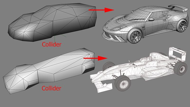
game, especially if 20 cars collide in a turn at the same time. To optimize such scenarios, a simple collider shape is used to calculate collisions between car bodies and track objects. The collider shape must be a simple solid object with as low polygon count as possible, without any UV or texture. The collider’s pivot must be in the 0,0,0 coordinates and have the same orientation as the wheel dummies. Rules for collider objects:
- The collider should have no more than 40/60 triangles.
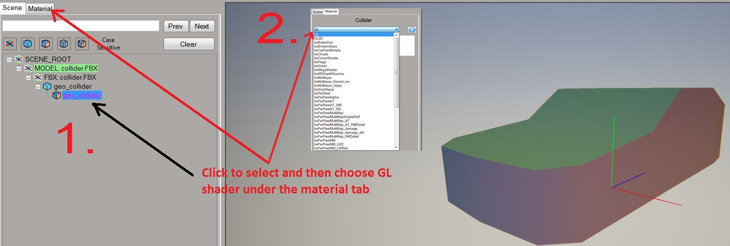
- A material called “GL” must be assigned to the collider inside the editor. This is a special material specifically made for a mesh that is not rendered. Meshes with this material are used only for collisions.
- The collider must not
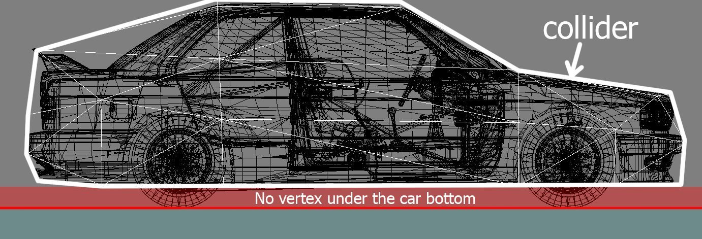
extend below the floor of the car. 4) The collider must have no holes. The mesh must be completely closed. Once the collision mesh is done, simply export the kn5 from the editor, using name “collider.kn5”. Make sure you save with NO textures! The file must be placed in the same folder as the car LODs with the name collider.kn5.